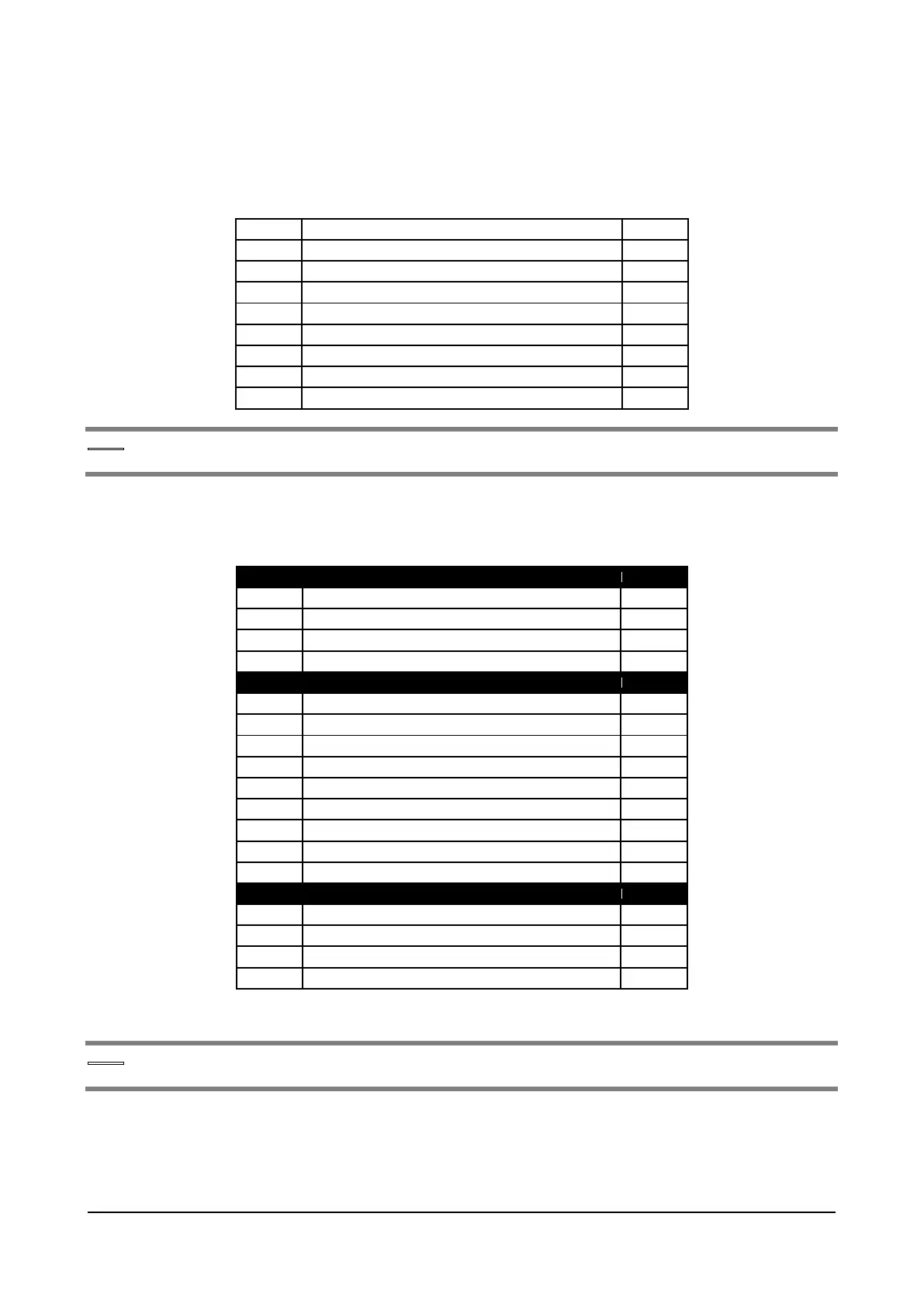
5.2.5.4 Jumpers
The configuration of the configuration Jumpers can be changed ONLY by Gefran personnel.
Unauthorized changes will invalidate the warranty.
Disables heatsink overtemperature monitor
Enables function of 230VAC line power supply
Connects J3 shield with ground
Connects 0V control with 0V_24 I/O
For the position of the Jumpers, see “Figure 5.2.5.1: Position of Switches, LEDs and Jumpers on R-
PSM card” .
5.2.5.5 Led R-PSM card
Presence of DC-Link voltage
DC-Link voltage above UNDERVOLTAGE limit
Power supply OK (no alarms – excluding UV)
Phase loss or Main loss alarm
Heatsink overtemperature alarm
FPGA configuration in progress
Wrong line frequency alarm
Cable inserted to synchronize J3 master and J5 SLAVE
“POWER SUPPLY STATE” functions
Bit S0: codes STATE of power supply (LSB)
Bit S1: codes STATE of power supply
Bit S2: codes STATE of power supply (MSB)
For the position of the Jumpers, see “Figure 5.2.5.1: Position of Switches, LEDs and Jumpers on R-
PSM card”.
Addendum to the ADV200 / ADV200WA QS Instruction books Page 9 of 20
 Loading...


