Table 5.2.5.1: R-PSM card terminal box
TB1 terminal strip
Terminal Designation Function Electrical specifications
23 ENABLE ENABLE digital input of the pre-charge control 5mA @ +24Vdc (+20% max, -20% min)
52 ENABLE in COM ENABLE common digital input -
32 Digital Out 1 Drive OK 24V / 20mA typ (40mA max)
33 Dig Out Com Common Digital Out 1 and Digital Out 2 -
34 0V24 Out Reference point for power supply -
35 +24V Out Power supply output 150mA resettable fuse
36 Digital Out 2 Digital output : Factory preset as Mains Loss 24V / 20mA typ (40mA max)
37 Dig Out Supply Power supply for digital outputs
70 - 72 Relay 1 Factory preset as Precharge OK 250Vac - 30Vdc - 0.5A
Terminal strip
TB1
Cable Cross Section (flexible conductor)
(min)
0.2 ... 2.5 24 ... 12 7 0.5
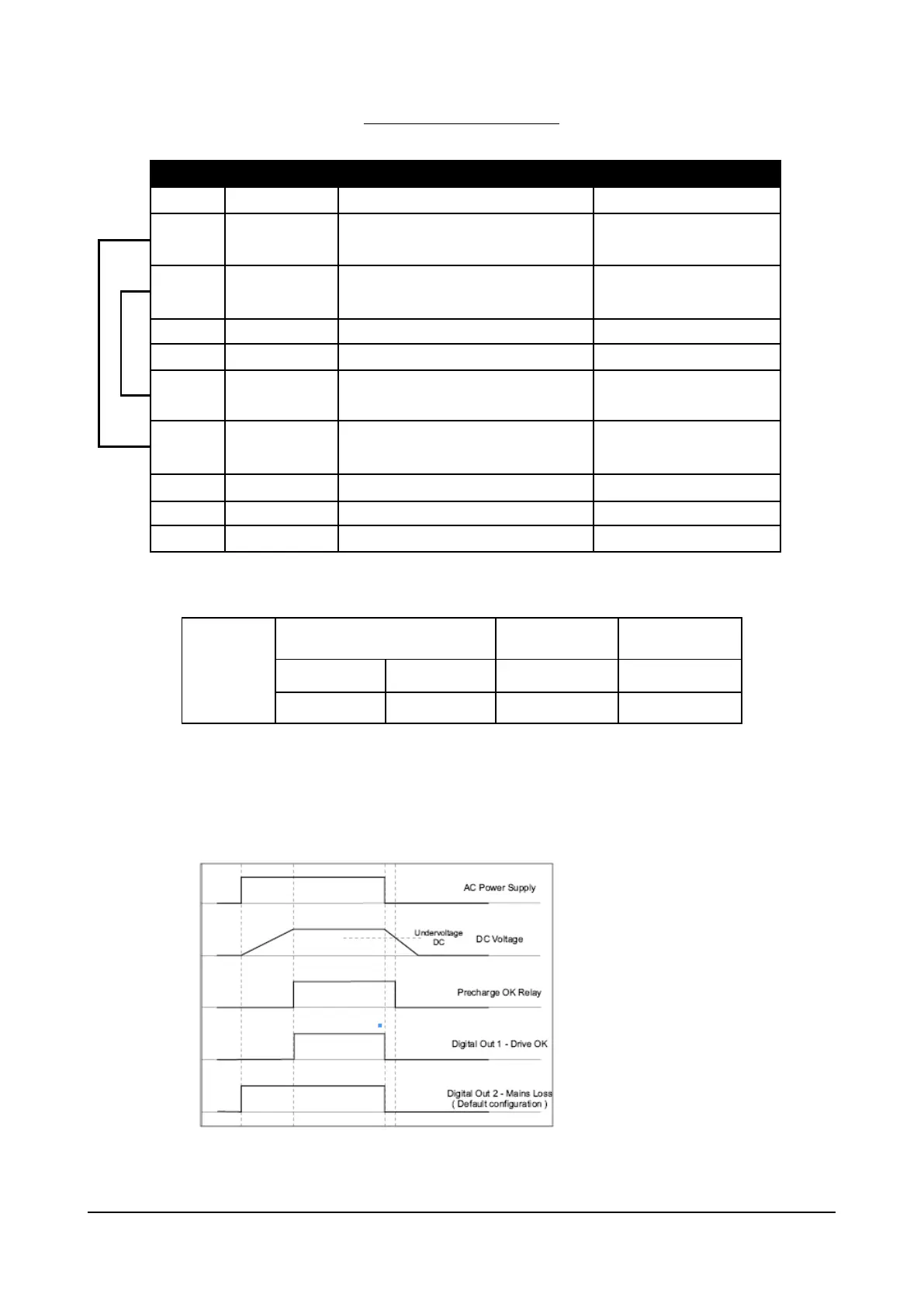
5.2.5.2 Behavior of Pre-charge OK Relay-Digital Out 1, Digital Out 2 at “PowerOn” and “PowerOff”
Addendum to the ADV200 / ADV200WA QS Instruction books Page 6 of 20
 Loading...


