5.2.5.1 Ingressi/Uscite Scheda di regolazione R-PSM
Gli switch e i jumper presenti sulla scheda R-PSM sono configurati in fabbrica, se il modulo viene utilizzato secondo le sue
caratteristiche di alimentazione standard:
ADV200-…-4 = 400VAC / 50Hz
ADV200-…-6 = 690VAC / 50Hz
l’impostazione non deve essere modificata. In caso di alimentazione diversa dallo standard è necessario fare riferimento alle
tabelle di configurazione più avanti riportate.
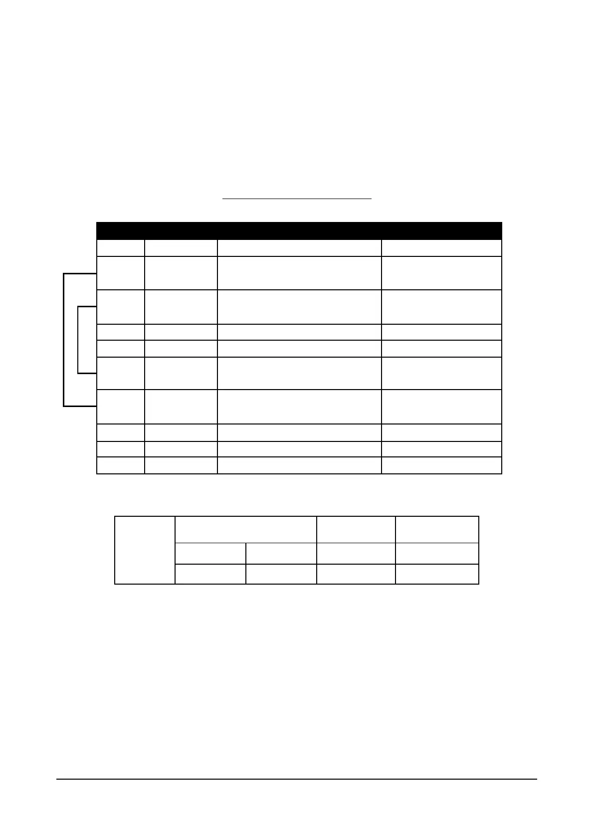
Table 5.2.5.1: Morsettiera della scheda R-PSM
Morsettiera TB1
Morsetto Designazione Funzione Specifiche Elettriche
23 ENABLE Ingresso digitale di ENABLE 5mA @ +24Vdc (+20% max, -20% min)
52 ENABLE in COM Comune ingresso digitale ENABLE -
32 Digital Out 1 Drive OK 24V / 20mA typ (40mA max)
33 Dig Out Com Comune Digital Out 1 e Digital Out 2 -
34 0V24 Out Comune Alimentazione I/O -
35 +24V Out Alimentazione I/O 150mA fusibile ripristinabile
36 Digital Out 2 Uscita Digitale: Dafault programmato come Mains Loss 24V / 20mA typ (40mA max)
37 Dig Out Supply Ingresso Alimentazione Uscite digitali
70 - 72 Relay 1 Programmato di fabbrica come Precharge OK 250Vac - 30Vdc - 0.5A
Morsettiera
TB1
Sezione dei cavi (conduttore flessibile)
Coppia di serraggio (min)
(min)
0.2 ... 2.5 24 ... 12 7 0.5
Addendum to the ADV200 / ADV200WA QS Instruction books Page 14 of 20
 Loading...


