Relay 1 – Precharge OK (factory setting)
The relay between terminals 70 – 72 closes at the end of the pre-charge phase and opens when DC voltage drops below the
DC Undervoltage threshold. Wiring of the OK relay contact (70 - 72) in series with the Enable chain of the ADV200 regulation
card is recommended.
Digital Out 1 – Drive OK
Digital output 1 connected to terminal 32 goes high at the end of the pre-charge phase and goes low under one of the
following conditions:
- Power failure
- Lack of a power supply phase
- Mains frequency out of range ( > ±5%). This condition occurs only during the power-on phase.
- Presence of Enable command at terminal 23
Digital Out 2 – Mains Loss (factory setting)
Digital output 2 connected to terminal 36 goes high at Power On and goes low under one of the following conditions.
- Power failure
- Lack of a power supply phase
5.2.5.3 R-PSM card configuration switches
The jumpers and switches on these cards are factory-set. If the module is used according to its standard power supply
characteristics the settings should not be changed.
The R-PSM card has three 4-position configuration switches.
The following tables show all of the permitted combinations.
Legend:
0 OPEN
1 CLOSE
(*) Default setting for models ADV200 -...-4,
(**) Default setting for models ADV200-...-6.
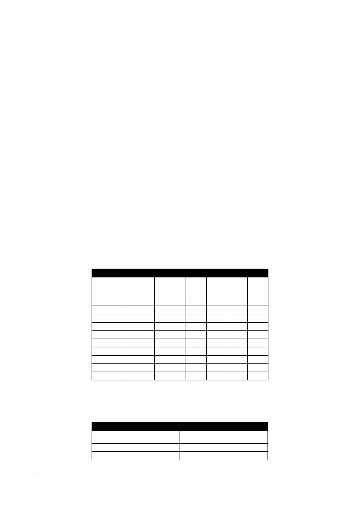
S1 - Mains voltage configuration switches
Mains voltage
DC
undervoltage
trip threshold
undervoltage
return
S1-1 S1-2 S1-3 S1-4
The correct selection of mains voltage is very important for correct setting of UNDERVOLTAGE limits.
The same value set has to be carried out on PAR560 (DRIVE CONFIG MENU)
S2 - Mains frequency configuration switch
Mains frequency [Hz] S2-1
Addendum to the ADV200 / ADV200WA QS Instruction books Page 7 of 20
 Loading...


