5-4
Parameter setting
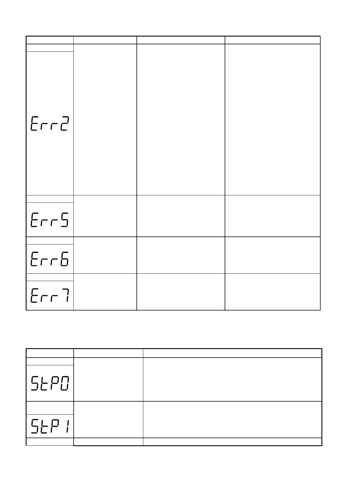
error
1. 00-13 is within the range
of (11-08 ±11-11)
OR (11-09 ±11-11)
OR (11-10 ±11-11)
2. 00-12≦00-13
3. 00-05/00-06 or 00-00 /
10-01 set the same value
4. Modifying parameters
01-01~01-09 when
01-00≠ 7.
5. a.If this parameter is
parameterized for both
functions (AVI/PTC) at
the same time.
b.PTC function is
enabled by setting
08-10≠0.
6. Parameter password
function (13-07) set
1. modify11-08~11-10 or 11-11
2. 00-12>00-13
3.set 00-05 / 00-06 or 10-00 /
10-01 to be different value
4.set 01-00=7
5.PTC function source can not
be the same as frequency
source or PID command via
AVI.
6. Please set correct password
Modification of
parameter is not
available in
communication
1.Control command sent
during communication.
2.Attempt to modify the
function 09-02~ 09-05
during communication
1.Issue enable command
before communication
2.Set parameters 09-02~
09-05 function before
communication
Communication
failed
2.Communication
Parameter setting error.
3.Incorrect communication
1. Check hardware and wiring
2.Check Functions(09-00~
09- 05).
Parameter conflict
function 13-00/13-08.
2. Voltage and current
detection circuit is
If reset is not possible, please
consult with the supplier.
5.1.3 Special conditions
Zero speed at stop
STP0 is a message displayed on keypad (and on
communication) to signal to the user that the motor doesn’t
move because the preset frequency is very low.
In V/f mode, STP0 comes out at less than 1.3Hz (50Hz set)
and at less than 1.5Hz (60Hz set)
In SLV mode, STP0 comes out at less than 1Hz.
StP1
Fail to start directly
On power up.
1. If the inverter is set for external terminal control mode
(00-02/00-03=1) and direct start is disabled (07-04=1)
2. The inverter cannot be started and will flash STP1.
3. The run input is active at power-up, refer to descriptions
1. If the Stop key is pressed while the inverter is set to
 Loading...


