24
880397M_MSW_GFX4-GFXTERMO4_08-2018_ENG
ALARMS
GENERIC ALARMS AL1, AL2, AL3 and AL4
Four generic alarms are always available and can perform various functions.
Typically, alarm AL.1 is defined as minimum and AL.2 as maximum.
These alarms are set as follows:
- select the reference variable to be used to monitor the value (parameters A1.r, A2.r, A3.r and A4.r): the origin of the
variable can be chosen from the process variable PV (generally linked to the main input), the ammeter input, the voltmeter
input, the auxiliary analog input, or the active setpoint.
- set the value of the alarm setpoint (parameters AL.1, AL.2, AL.3 and AL.4).
This value is used for comparison with the reference variable value: it can be absolute or indicate a shift from the variable in
case of deviation alarm.
- set the hysteresis value for the alarm (parameters Hy.1, Hy.2, Hy.3 and Hy.4):
the hysteresis value defines a band for safe re-entry of the alarm condition: without this band, the alarm would be deactivated
as soon as the reference variable re-entered the setpoint limits, with the possibility of generating another alarm signal in the
presence of oscillations of the reference signal around the setpoint value.
- select alarm type:
- absolute/deviation: if the alarm refers to an absolute value or to another variable (for example, to the setpoint).
- direct/reverse: if the reference variable exceeds the alarm setpoint in the “same direction” as the control action or not. For
example, the alarm is direct if the reference variable exceed the upper setpoint value during heating or assumes values below
the lower setpoint during cooling. In the same manner, the alarm is reverse if the reference variable assumes values below
the lower setpoint during heating or exceeds the setpoint during cooling.
- normal/symmetrical: if band value is subtracted or added, respectively, to/from the upper and lower limit of the alarm setpoints
or indicates a higher and lower band compared to the alarm setpoint.
- with/without disabling at switch-on: if you want to check the reference variable value at system switch-on or wait until the
variable enters the control window.
- with/without memory: if the alarm signal persists even when the cause has been eliminated or stops when the variable returns
to normal values.
- definition of upper and lower limits for setting absolute alarms: if the alarm is used to check that the operator does
not set a setpoint value outside a certain band during multiset operation. The above concepts are better explained in the fol-
lowing figures:
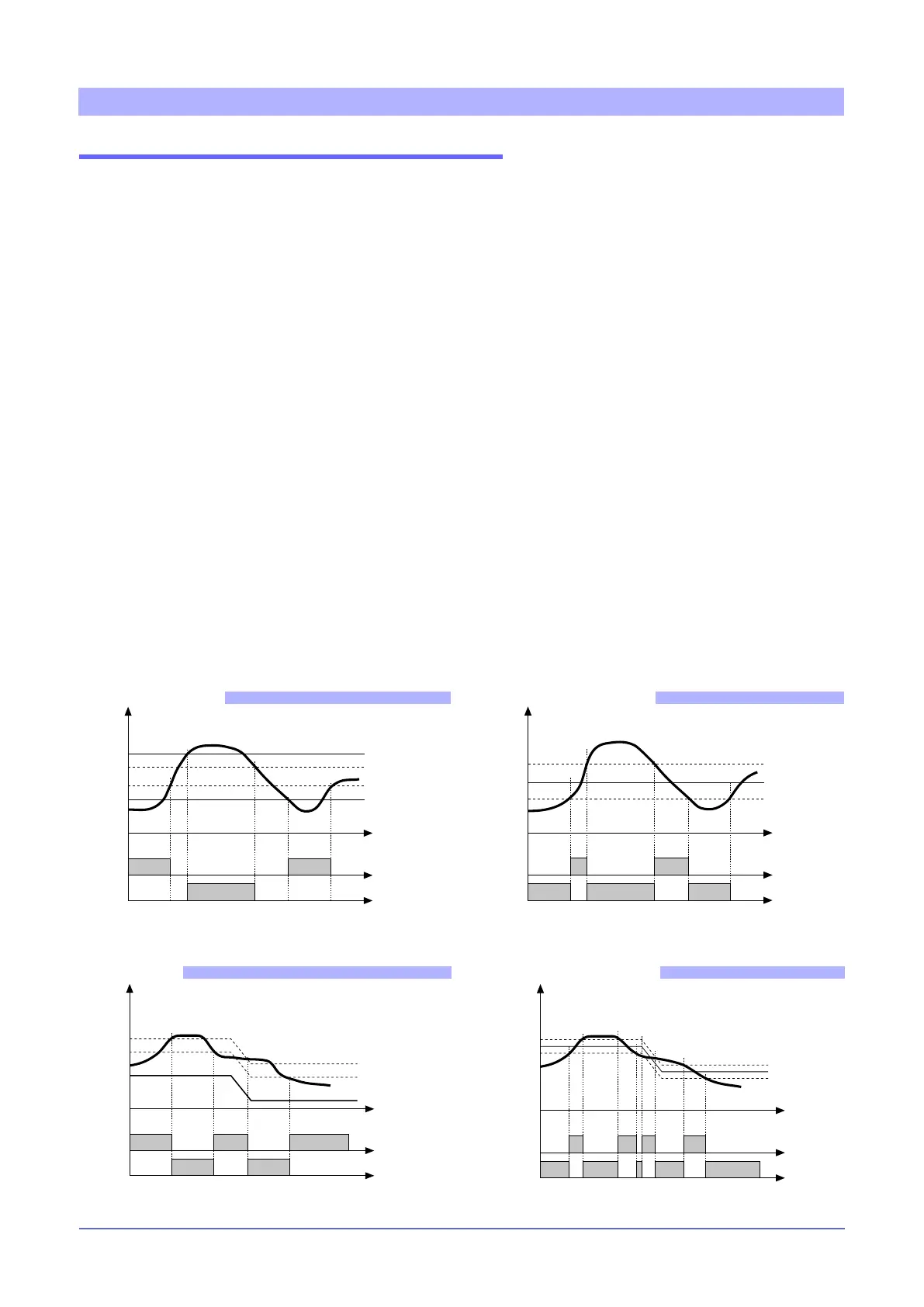
time
AL1 + Hyst1
AL2 + Hyst2
AL2
AL1
allarm 1
allarm 2
(*)
For AL1 reverse absolute alarm (low) with positive Hyst1, AL1 t = 1 (*) = OFF
if disabled at switch on
For AL2 direct absolute alarm (high) with negative Hyst2, AL2 t = 0
Normal absolute alarm
For AL1 = symmetrical inverse absolute alarm with Hyst1, AL1 t = 5
For AL1 = symmetrical direct absolute alarm with Hyst1, AL1 t = 4
Minimum hysteresis = 2 scale points
Inverse
Direct
AL1
AL1 + [ Hyst1 ]
AL1 - [ Hyst1 ]
time
Symmetrical absolute alarm
For AL1 = normal inverse deviation alarm with negative Hyst 1, AL1 t = 3
For AL1 = normal direct deviation alarm with negative Hyst 1, AL1 t = 2
SP+AL1
SP
Inverse
Direct
time
Hyst1
Deviation alarm
For AL1 = Symmetrical inverse deviation alarm with Hyst 1, AL1 t = 7
For AL1 = Symmetrical direct deviation alarm with Hyst 1, AL1 t = 6
time
SP+AL1
SP
Inverse
Direct
SP-AL1
Symmetrical deviation alarm
 Loading...


