5980397M_MSW_GFX4-GFXTERMO4_08-2018_ENG
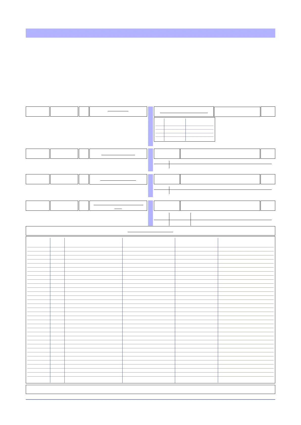
Virtual instrument control is activated by means of parameter hd.1.
By setting parameters S.In and S.Ou you can enable the writing of some parameters via serial line, set the value of
inputs and the state of outputs.
You have to enable alarm setpoints AL1, ..., AL4 when write operations are continuous, and you don’t have to keep
the last value in eeprom.
Enabling the PV input means being able to exclude the local Tc or RTD acquisition and replace it with the value writ-
ten in the register VALUE_F.
Enabling digital input IN lets you set the state of this input, for example to run MAN/AUTO switching with the writing
of bit 7 in the register V_IN_OUT.
Likewise, you can set the on/off state of outputs OUT1, ..., OUT10 and of the LEDs by writing bits in the register
V_IN_OUT.
191
hd.1
R/W
Enable multiset
instrument control via serial
0
Table for multiset/ virtual instrument
Enable Enable
Multiset virtual instrument
0
1 X
2 X
3 X X
VIRTUAL INSTRUMENT CONTROL
224
s.In
R/W
Control inputs from serial
0 ... 255
0
Inputs InTA In.2 - In.1 AL4 AL3 AL2 AL1
Bit 7 6 5 4 3 2 1 0
225
s.0v
R/W
Control outputs from serial
0 ... 1023
0
Outputs Out10 Out9 Out8 Out7 Out6 Out5 Out4 Out3 Out2 Out1
Bit 9 8 7 6 5 4 3 2 1 0
628
s.LI
R/W
Control LEDs and digital inputs from
serial
0 ... 1023
0
Input LED
D2 D1 O4 O3 O2 O1 D2 D1 ER RN
Bit 9 8 7 6 5 4 3 2 1 0
Parameter bit Resource enabled Address of Format Name of register
image register
S.In 0 Alarm setpoint AL1 341 word AL1_RAM
1 Alarm setpoint AL2 342 word AL2_RAM
2 Alarm setpoint AL3 343 word AL3_RAM
3 Alarm setpoint AL4 321 word AL4_RAM
4 Input In.1 347 word VALUE_F
6 Input In.2 348 word VALAUX_F
7 Input In.TA 685 word VALTA_F
S.Ou 0 Output OUT 1 344 word, bit 0 V_IN_OUT
1 Output OUT 2 344 word, bit 1 V_IN_OUT
2 Output OUT 3 344 word, bit 2 V_IN_OUT
3 Output OUT 4 344 word, bit 3 V_IN_OUT
4 Output OUT 5 (relays) 344 word, bit 4 V_IN_OUT
4 Output OUT 5 (continuous) 639 word SERIAL_OUT5C*
5 Output OUT 6 (relays) 344 word, bit 5 V_IN_OUT
5 Output OUT 6 (continuous) 640 word SERIAL_OUT6C*
6 Output OUT 7 (relays) 344 word, bit 6 V_IN_OUT
6 Output OUT 7 (continuous) 641 word SERIAL_OUT7C*
7 Output OUT 8 (relays) 344 word, bit 7 V_IN_OUT
7 Output OUT 8 (continuous) 642 word SERIAL_OUT8C*
8 Output OUT 9 344 word, bit 8 V_IN_OUT
9 Output OUT 10 344 word, bit 9 V_IN_OUT
S.LI 0 Led RN 351 word, bit 0 V_X_LEDS
1 Led ER 351 word, bit 1 V_X_LEDS
2 Led D1 351 word, bit 2 V_X_LEDS
3 Led D2 351 word, bit 3 V_X_LEDS
4 Led O1 351 word, bit 4 V_X_LEDS
5 Led O2 351 word, bit 5 V_X_LEDS
6 Led O3 351 word, bit 6 V_X_LEDS
7 Led O4 351 word, bit 7 V_X_LEDS
8 Input D1 344 word, bit 10 V_IN_OUT
9 Input D2 344 word, bit 11 V_IN_OUT
Table of virtual register addresses
* the value to be set is in the range 0...1000 if the corresponding rL.x is congured “0” or in the range 0...-1000 if the corresponding rL.x is congured “1”.
+16 For Heat/Cool control Ctr only: CT connected to cool output
 Loading...


