,167$//$7,21
(YDFXDWLRQXVLQJEDODQFHGIOXH
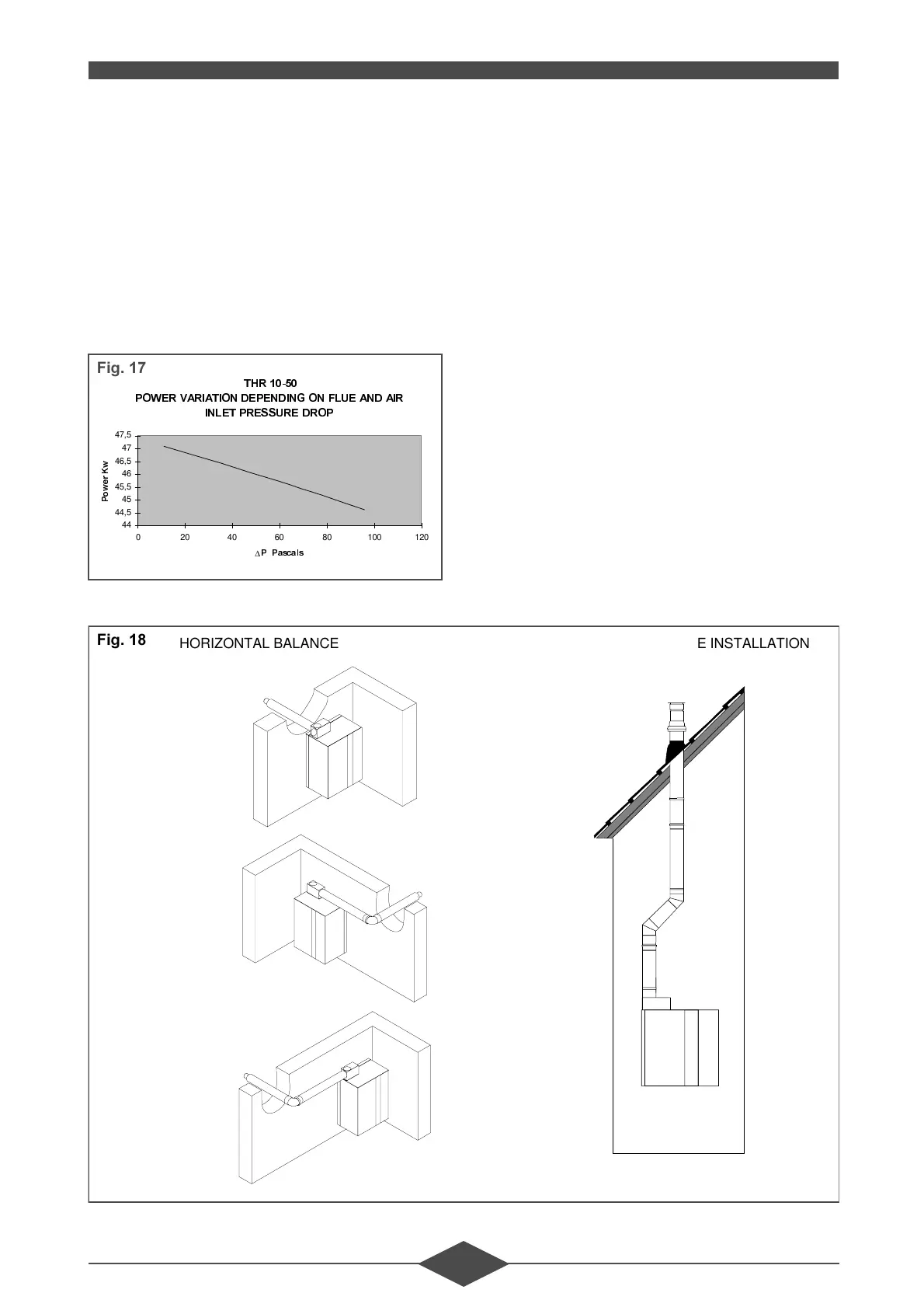
3RZHU
Power is automatically reduced by means of the air/
gas servo-control system. No systematic adjust-
ment is required when commissioning the installa-
tion. Only the usual CO and CO
2
checks should be
carried out (see table in § 3 - V - COMMISSION-
ING). The maximum
∆P of 100 Pa is obtained with
a vertical balanced flue DN 80/125 length 4 metres
with two 45° elbows.
*HQHUDOLQVWUXFWLRQV
The sealed combustion circuit THR boiler connect-
ed to a vertical balanced flue is independent of the
ventilation conditions in the room where it is in-
stalled.
Two concentric tubes supply air to the burner and
evacuate the combustion products. The conduits
can be bent, allowing the system to be adapted to
most installation situations.
The flue terminal cover is specially designed to with-
stand wind from all directions as well as rain and
snow.
([DPSOHDVVHPEO\
7+5
32:(5
9$5,$7, 2 1
'(3(1', 1*
21
)/8(
$1'
$,5
,1/ (7 35(6685( '523
44
44,5
45
45,5
46
46,5
47
47,5
020406080100120
∆
33DVFDOV
3
R
Z
H
U
.
Z
)LJ
)LJ
HORIZONTAL BALANCED FLUE INSTALLATION VERTICAL BALANCED FLUE INSTALLATION
 Loading...