&200,66,21,1*
&219(56,216(7
This operation should be carried out by a qualified
professional equipped with a calibrated combustion
analyser.
Before each intervention, switch off electrical and
gas supplies.
The boiler is pre-set in work for Natural gas H (G20)
or for LPG (G31).
&RQYHUVLRQIURP1DWXUDOJDV+WR/3*
- Replace gas reducer Ø 7.30 (Natural gas H) by
gas reducer Ø 5.60 at the gas valve outlet
(fig. 23).
- Insert air ring Ø 31 into the burner sleeve (fig. 23).
- Check combustion parameters (see table § 3 - V
- COMMISSIONING).
- If necessary, proceed to the adjustment of gas
valve according the process described hereafter
(a CO
2
/CO analyser calibrated beforehand is
necessary).
&RQYHUVLRQIURP/3*WR1DWXUDOJDV+
- Replace gas reducer Ø 5.60 by gas reducer
Ø 7.30 (Natural gas H) at the gas valve outlet
(fig. 23).
- Remove air ring Ø 31 from the burner sleeve
(fig. 23).
- Check combustion parameters (see table § 3 - V
- COMMISSIONING).
- If necessary, proceed to the adjustment of gas
valve according the process described hereafter
(a CO
2
/CO analyser calibrated beforehand is
necessary).
$GMXVWPHQWSURFHVV
- Commission the burner by pushing for about
5 seconds on button A of the control board -
Switch to flashing "7" on the display. Check the
gas tightness with a foaming product (inlet con-
nections of the boiler, inlet/outlet of the gas valve,
outlet of the gas tube).
- Gradually set the sanitary potentiometer to the
right hand stop point (burner at maximum rate).
- Check the CO
2
/CO rate according to the table § 3
- V - COMMISSIONING. The flow rate at the max-
imum setting is not adjustable, it’s given by the
gas reducer.
- Set the sanitary potentiometer to the left hand
stop point (burner at minimum rate).
- Check the CO
2
/CO rate according to the table § 3
- V - COMMISSIONING and adjust the V screw if
necessary (screwing increases the gas flow, un-
screwing reduces it).
Reminder:
- Before adjusting the minimum rate (screw K),
wait for a stable CO
2
/CO reading on the analyser.
Switch from minimum to maximum rate several
times to ensure that the adjustment has been
made correctly. Use an accurately calibrated
analyser.
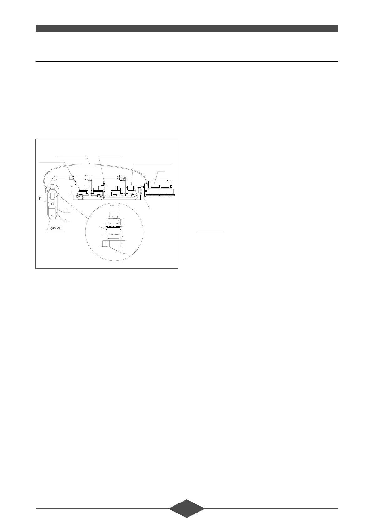
.
3
3
gas valve
Ignition electrode
Air/Gas servo system
Ionisation probe
Burner THR 10-50 GN/GP
Fan
Brass air ring
31
only for
propane gas
∅
Gas valve
Flange
O-ring
Gas reducer
O-ring
Gas valve
flange
Gas
reducer
)LJ
 Loading...