23(5$7,21
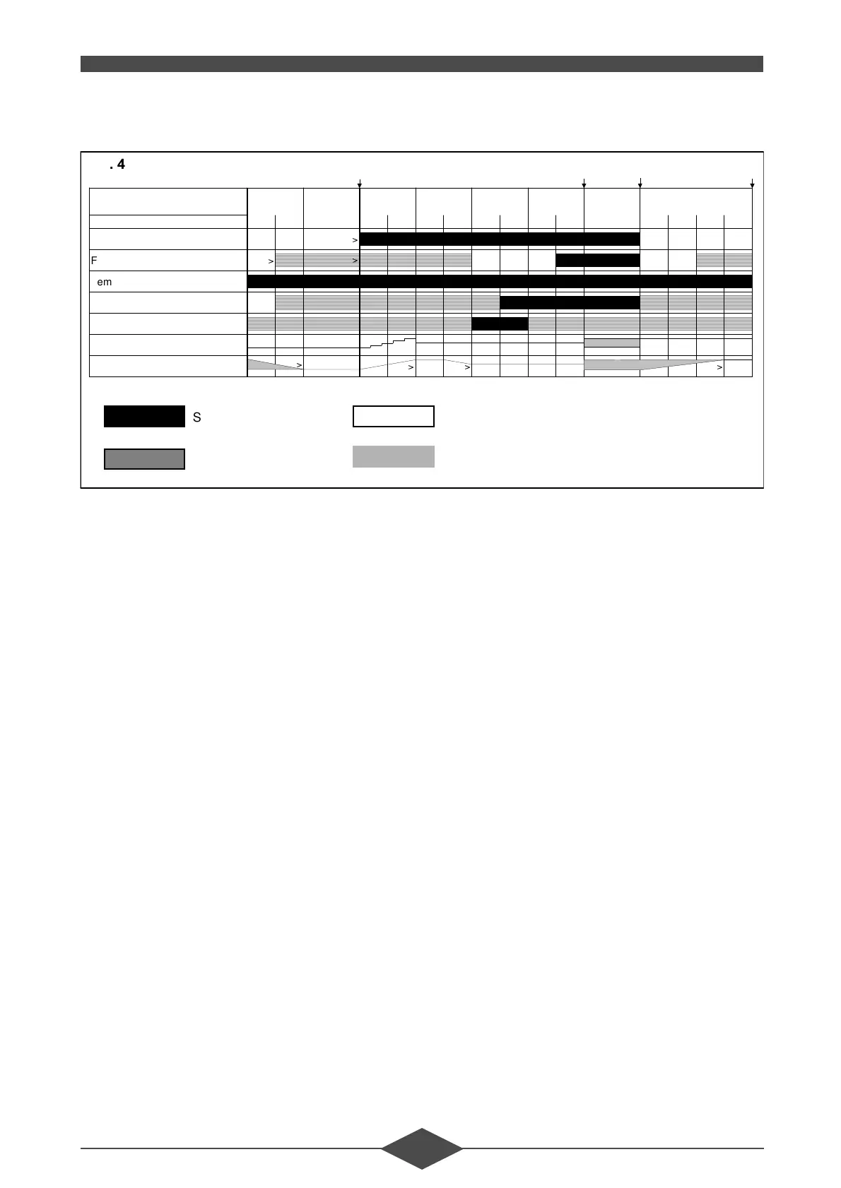
2SHUDWLQJGLDJUDP
3URJUDPPHVHTXHQFH
3KDVH67$1'%<
The boiler is on standby awaiting a demand for
heat.
A: Start-up instruction.
I is given by the boiler regulator or by the domes-
tic hot water regulator.
3KDVH)DQVSHHGULVHWLPH
This time ends as soon as the fan motor speed
reaches the load programmed for preventilation.
3KDVH3UHYHQWLODWLRQWLPH
3KDVH7DSHULQJWLPH
This time ends as soon as the programmed igni-
tion load is reached.
3KDVH3UHLJQLWLRQWLPHV
Appearance of the ignition arc prior to opening
the gas valve, which occurs at the start of phase
35.
3KDVH6DIHW\WLPHV
A flame signal should be present (ionization cur-
rent > 2.8 µA) before the safety time has elapsed.
If this does not occur, another ignition attempt is
made.
3KDVH%&%XUQHURSHUDWLRQ
Burner operation following a demand for hot wa-
ter (display 6) or heating (display 7).
3KDVH&'6KXWGRZQ
The change of operating position to standby is re-
ferred to as a “shut-down” and occurs when the
demand for heat disappears. The gas valve clos-
es and the combustion residues are evacuated
by post-ventilation.
3KDVH%ORFNLQJWLPH
Blocking time, for test purposes (about 2 s).
3KDVH&ORVXUHWLPH
Time required to arrive at the programmed air
flow rate.
3KDVH3RVWYHQWLODWLRQWLPHV
The fan remains on during the post-ventilation
phase.
3KDVH5HWXUQWRLQLWLDOSRVLWLRQ
Obligatory passage from the shut-down position
to standby. This phase is also used to bring the
gas control box to the standby position after ex-
ceptional events such as a reset.
ABCD
Readout
90/123456./7. 8
Phase number 60 61 10 30 31 32 33 34 35 36 37 40 50 51 52 53
Heating demand
!
Flame signal
!
!
Temp. limiting safety device
Gas valve
Ignition
PWM
Fan speed
!
!! !
)LJ
Signal required
Signal unacceptable
> Condition required to move on the next stage
Range of possible speeds
 Loading...