Page 11
GENERAL INFORMATION
SECTION 1.1
GENERATOR FUNDAMENTALS
A SIMPLE AC GENERATOR
Figure 4 shows a very simple AC Generator. The gen-
erator consists of a rotating magnetic field called a
ROTOR and a stationary coil of wire called a STATOR.
The ROTOR is a permanent magnet which consists of
a SOUTH magnetic pole and a NORTH magnetic pole.
As the MOTOR turns, its magnetic field cuts across
the stationary STATOR. A voltage is induced Into
the STATOR windings. When the magnet's NORTH
pole passes the STATOR, current flows in one direc-
tion. Current flows in the opposite direction when the
magnet's SOUTH pole passes the STATOR. This con-
stant reversal of current flow results in an alternating
current (AC) waveform that can be diagrammed as
shown in Figure 5.
The ROTOR may be a 2-pole type having a single
NORTH and a single SOUTH magnetic pole. Some
ROTORS are 4-pole type with two SOUTH and two
NORTH magnetic poles. The following apply:
1. The 2-pole ROTOR must be turned at 3600 rpm to pro-
duce an AC frequency of 60 Hertz, or at 3000 rpm to
deliver an AC frequency of 50 Hertz.
2. The 4-pole ROTOR must operate at 1800 rpm to deliver
a 60 Hertz AC frequency or at 1500 rpm to deliver a 50
Hertz AC frequency.
Figure 4. A Simple AC Generator
CURRENT
VOLTAGE
ONE CYCLE
0
180
360
(+)
(-)
Figure 5. Alternating Current Sine Wave
A MORE SOPHISTICATED AC GENERATOR
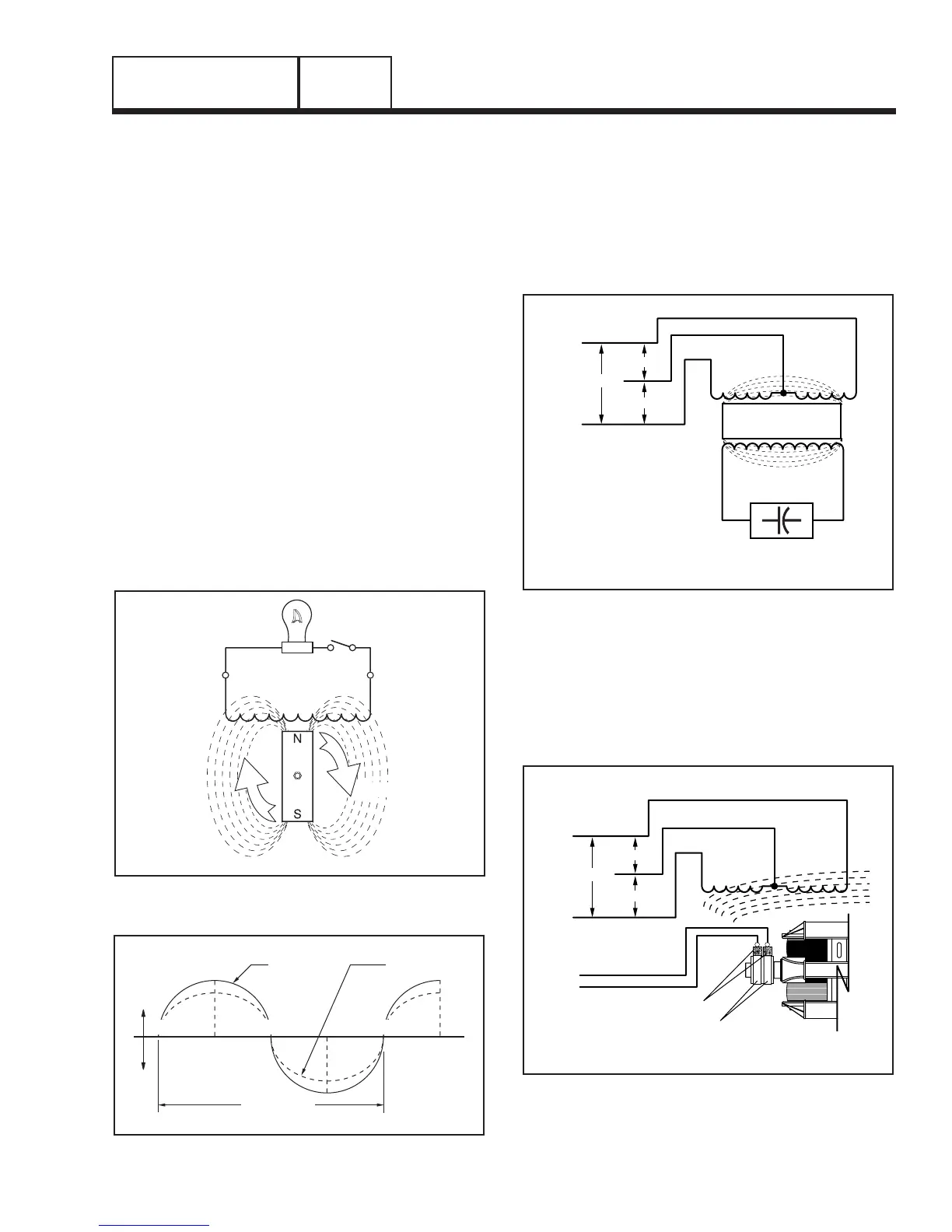
Figure 6 and 7 show two methods of creating alternat-
ing current that are implemented on GP Series por-
table generator product.
Figure 6 shows a consistent voltage being induced to
the rotor from a capacitor which is installed in series
with the DPE winding. As a result a regulated voltage
is induced into the STATOR.
STATOR
ROTOR
GENERATOR
120 VAC
120 VAC
+
-
AC OUTPUT
STATOR
240 VAC
CAPACITOR
Figure 6. Capacitive Discharge
Figure 7 shows a regulated direct current being deliv-
ered into the ROTOR windings via carbon BRUSHES
AND SLIP RINGS. This results in the creation of
a regulated magnetic field around the ROTOR. As
a result, a regulated voltage is induced into the
STATOR. Regulated current delivered to the ROTOR
is called “EXCITATION” current.
STATOR
BRUSHES
120 V
120 V
+
-
SLIP
RINGS
AC OUTPUTDC CURRENT
STATOR
240 V
Figure 7. Direct Excitation
PART 1
 Loading...


