SECTION 3.3
DIAGNOSTIC TESTS
Page 49
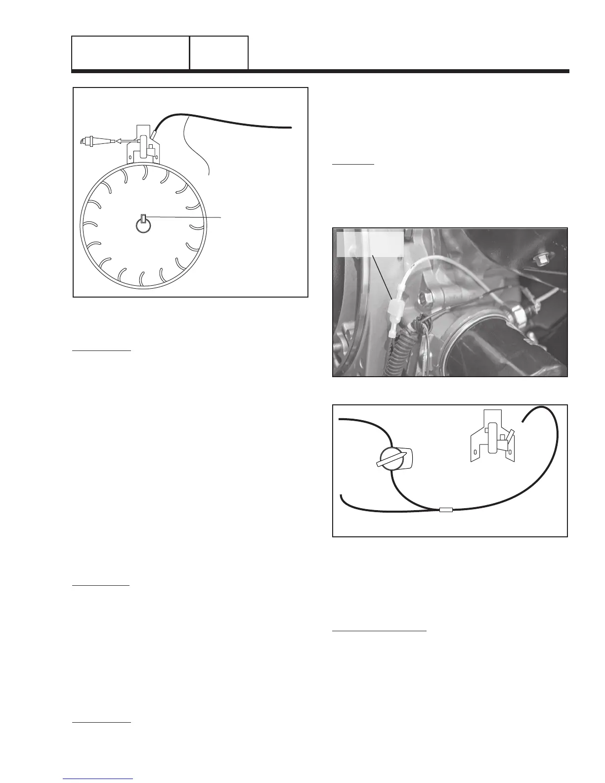
SPARK PLUG
ENGINE WIRE HARNESS
REMOVE LEAD
FLYWHEEL KEY
WIRE 18 TO
START-RUN-STOP SWITCH
(SHUTDOWN LEAD)
Figure 16. Engine Ground Harness
PROCEDURE:
1. Check the flywheel magnet by holding a screwdriver at
the extreme end of its handle and with its point down.
When the tip of the screwdriver is moved to within 3/4
inch (19mm) of the magnet, the blade should be pulled
in against the magnet.
2. For rough running or hard starting engines check the fly-
wheel key. The flywheel’s taper is locked on the crankshaft
taper by the torque of the flywheel nut. A keyway is pro-
vided for alignment only and theoretically carries no load
Note: If the flywheel key becomes sheared or even
partially sheared, ignition timing can change.
Incorrect timing can result in hard starting or fail-
ure to start.
TEST 39 – REMOVE WIRE 18 / SHUTDOWN
LEAD
DISCUSSION:
Wire 18 on all engines is used to shutdown the unit
when either the switch is placed in the OFF posi-
tion or a low oil condition has occurred. A ground
is applied to the magneto in both instances which
will inhibit spark and shutdown the unit. If a short to
ground exists on this wire the engine will be inhibited
from producing spark. This test will check the integrity
of the wire.
Note: The shutdown lead on units with the 389cc
engine will not be identified as Wire 18. Refer to
Figure 18 for identification of location.
PROCEDURE:
1. Turn off the fuel supply
2. Remove the flywheel cover so that the magneto is
exposed.
3. Disconnect Wire 18 from the magneto.
4. Repeat Test 25, “Check Ignition Spark.”
RESULTS:
1. If spark now occurs, Wire 18 has a short to ground.
Trace Wire 18 back to the START-RUN-STOP switch
and Oil Pressure Module (If so equipped).
2. If spark still does not occur, refer back to flow chart.
Figure 17. Wire 18 (410cc Engine)
OFF
ON
OFF-ON SWITCH
MAGNETO
SHUTDOWN HARNESS
WIRE 18
Figure 18. Shutdown Lead (389cc Engine)
TEST 40 – CHECK / ADJUST GOVERNOR
(389/206/163cc ENGINES)
INITIAL ADJUSTMENT:
1. Loosen the governor lever clamp bolt (See Figure
19).
2. While holding the governor lever in its full “INC. RPM”
position, rotate the governor shaft counter clockwise as
far as it will go.
Note: The governor shaft will only turn approx-
imately 20 degrees from a full clockwise posi-
tion. Do not apply excessive torque to the
governor shaft.
DC CONTROL
PART 3
 Loading...


