SECTION 3.3
DIAGNOSTIC TESTS
Page 51
GOVERNOR
SHAFT
PRIMARY
ADJUST
SCREW
GOVERNOR
CLAMP
BOLT
Figure 20. Engine Governor Adjustment (410cc Engine)
4. Connect a frequency meter across the generators AC
output leads.
5. Turn the primary adjust screw to obtain a frequency
reading of 62.5 Hz.
6. When frequency is correct at no load, check the AC volt-
age reading. If voltage is incorrect, the voltage regulator
may require adjustment if so equipped.
RESULTS:
1. If, after adjusting the engine governor, frequency and
voltage are good, tests may be discontinued.
2. If frequency is now good, but voltage is high or low, refer
back to flow chart.
3. If engine was overspeeding, check linkage and throttle
for binding. If no governor response is indicated refer to
engine service manual.
4. If engine appears to run rough and results in low fre-
quency, proceed to Problem 26 Flow Chart.
TEST 45 – CHECK OIL LEVEL SWITCH
DISCUSSION:
The 389cc engine does not utilize oil pressure to
lubricate the internal components. It utilizes a splash
type lubrication system. The switch should be nor-
mally open as long as the engine is filled with oil. The
switch will close when the oil level drops to low the
switch will close and ground out the magnetos inhibit-
ing spark until the oil level is raised.
PROCEDURE:
1. Verify that the oil level is full.
2. Refer to Figure 3 in Section 3.3. Unplug the wire from
the oil level switch.
3. Set VOM to measure resistance.
4. Connect one meter test lead to the previously discon-
nect wire coming from the oil level switch. Connect the
other meter test lead to frame ground. INFINITY should
be measured.
RESULTS:
1. A reading of CONTINUITY indicates that the switch is no
longer functioning and will need to be replaced.
TEST 46 – CHECK OIL PRESSURE SWITCH
If the engine cranks and starts, then shuts down
almost immediately, the cause may be one or more of
the following:
• Lowengineoillevel.
• Lowoilpressure.
• Adefectiveoilpressureswitch.
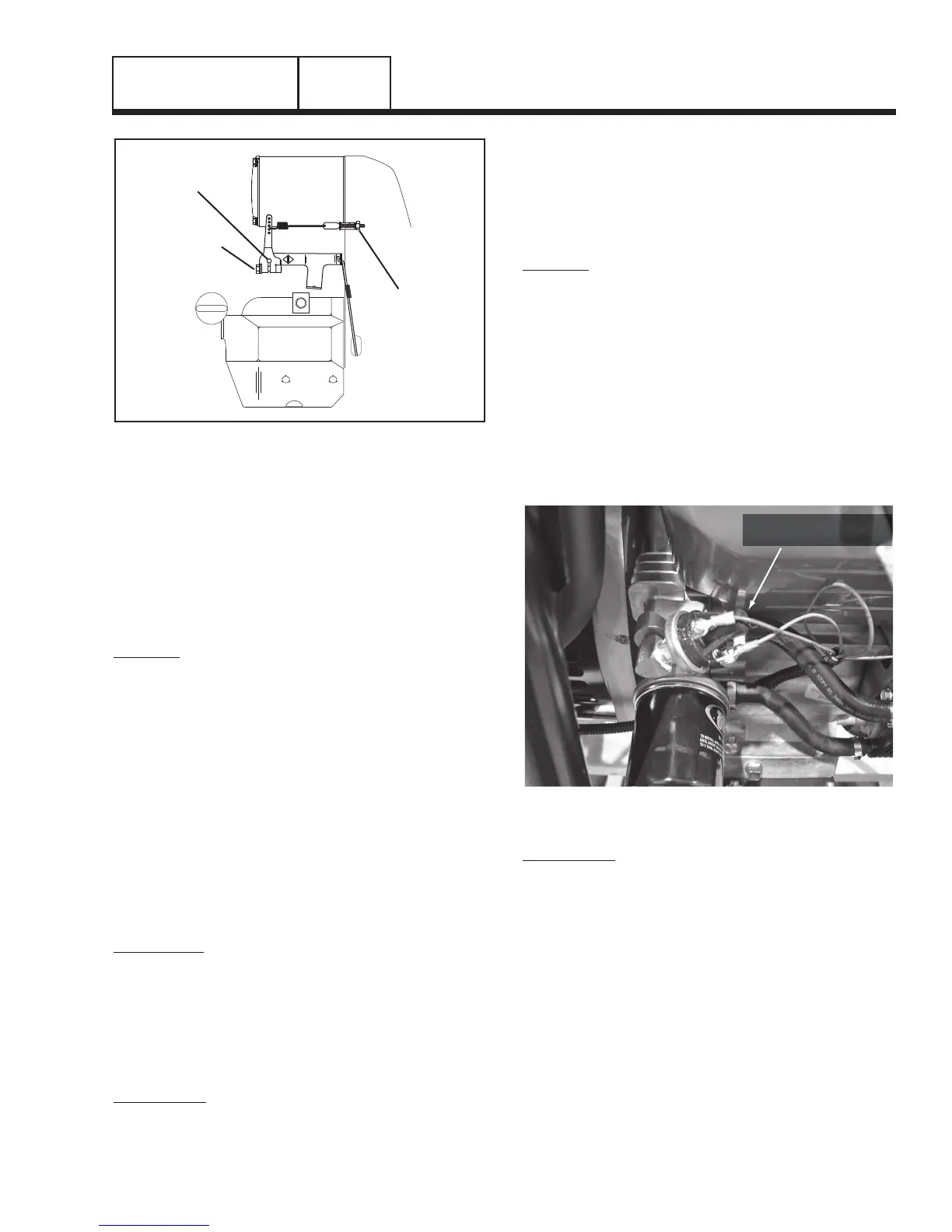
Figure 21. Low Oil Pressure Switch
PROCEDURE:
1. Check engine crankcase oil level.
a. Check engine oil level.
b. If necessary, add the recommended oil to
the dipstick FULL mark. DO NOT OVERFILL
ABOVE THE FULL MARK.
2. Do the following:
a. Disconnect Wire 86 and Wire 0 from the oil
pressure switch terminals. Remove the switch
and install an oil pressure gauge in its place.
b. Start the engine while observing the oil pres-
sure reading on gauge.
c. Note the oil pressure.
(1) Normal oil pressure is approximately 35-40
psi with engine running. If normal oil pres-
sure is indicated, go to Step 4 of this test.
DC CONTROL
PART 3
 Loading...


