Page 50
3. Tighten the governor lever clamp bolt to 110 inch-
pounds.
RUNNING ADJUSTMENT:
After completing the initial adjustment, final adjust-
ment is accomplished with the engine running under
no-load.
1. Turn the speed adjustment screw counter clockwise
three full turns to avoid a possible engine overspeed
condition.
2. Start the engine and let it warm up and stabilize under
no-load.
3. Connect an AC frequency meter to one of the AC output
receptacles. No-load frequency should be between
62.0 - 62.5 hertz.
4. If the frequency/RPM are incorrect, turn the speed adjust
screw until frequency/RPM is within limits. Turn clock-
wise to increase frequency/RPM, counter clockwise to
decrease the frequency/RPM (see Figure 19).
5. After adjustment is complete add a drop of removable
loctite (Loctite 241) to the threads of the speed adjust
screw (see Figure 19).
TEST 41 – CHECK / ADJUST GOVERNOR
(410cc ENGINE)
DISCUSSION:
The generator AC frequency output is directly pro-
portional to the speed of the rotor. A two-pole rotor
(having a single north and a single south magnetic
pole) will produce an AC frequency of 60 hertz at
3600 RPM.
The generator is equipped with a “voltage over fre-
quency” type AC voltage regulator. The units AC out-
put voltage is generally proportional to AC frequency.
A low or high governor speed will result in a corre-
spondingly low or high AC frequency and voltage out-
put. The governed speed must be adjusted before any
attempt to adjust the voltage regulator is made.
PROCEDURE
1. Loosen the governor clamp bolt (Figure 20).
2. Hold the governor lever at its wide open throttle position,
and rotate the governor shaft clockwise as far as it will
go. Then, tighten the governor lever clamp bolt to 70
inch-pounds (8 Nm).
3. Start the generator; let it stabilize and warm up at
no-load.
PART 3
DC CONTROL
SECTION 3.3
DIAGNOSTIC TESTS
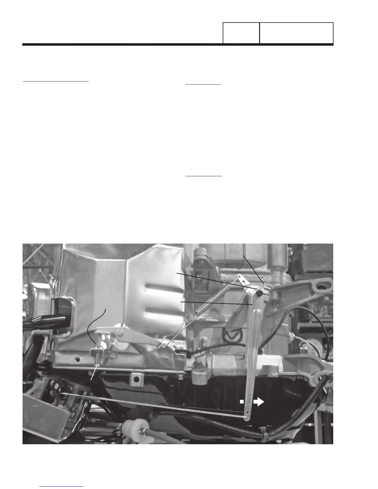
GOVERNOR SHAFT
GOVERNOR
CLAMP BOLT
GOVERNOR LEVER
APPLY
LOCTITE
HERE
SPEED ADJUST SCREW
INCREASE RPM
Figure 19. Governor Adjustment Points (389cc Engine)
 Loading...


