PART 2
Page 24
AC GENERATORS
SECTION 2.2
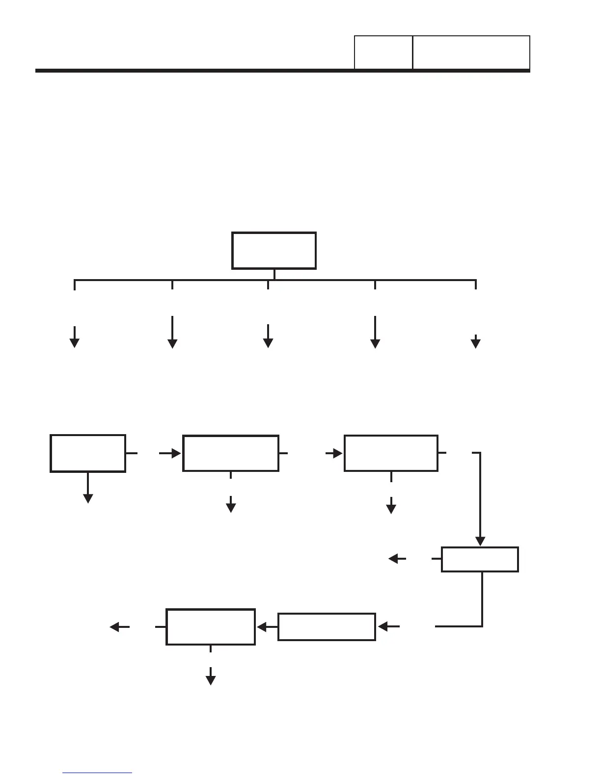
BRUSHED EXCITATION TROUBLESHOOTING FLOWCHARTS
GO TO PROBLEM 6 GO TO PROBLEM 5GO TO PROBLEM 5 GO TO PROBLEM 7
VOLTAGE &
FREQUENCY BOTH
HIGH OR LOW
FREQUENCY GOOD
VOLTAGE HIGH
ZERO VOLTAGE
ZERO FREQUENCY
FREQUENCY GOOD,
LOW OR RESIDUAL
VOLTAGE
TEST 1 - CHECK
NO LOAD VOLTAGE
& FREQUENCY
NO LOAD VOLTAGE &
FREQUENCY GOOD -
VOLTAGE/FREQUENCY
FALLS OFF UNDER LOAD
If Problem Involves AC Output
VERIFY ROTOR IS SPINNING,
GO TO PROBLEM 5
REPLACE
BRUSHES
STOP TESTING
BAD
BAD
BAD
GOOD
Problem 5 – Generator Produces Zero Voltage or Residual Voltage
TEST 2 – CHECK
MAIN CIRCUIT
BREAKER
RESET TO “ON”
OR REPLACE IF BAD
REPLACE COMPONENT
AS NEEDED
TEST 3 – CHECK
CONTINUITY OF
RECEPTACLE PANEL
TEST 5 – CHECK
BRUSHES
REPLACE
ALTERNATOR
REPLACE AUTOMATIC
VOLTAGE REGULATOR
TEST 12 – ADJUST
AUTOMATIC VOLTAGE
REGULATOR
ON
GOOD
GOOD
STOP TESTING
GOOD
BAD
RE-CHECK VOLTAGE
AT RECEPTACLE
PANEL
The GP series portable generators currently use
three different types of alternators. Two of the alterna-
tors are brushless capacitor type with different style of
capacitors (Configuration “A” and “B”). The third uti-
lizes a voltage regulator and a brushed excitation sys-
tem (Configuration “C”). To help with troubleshooting,
two sets of flow charts have been created for these
different styles of alternators.
Identify the configuration of the alternator being ser-
viced using Sections 1.3 and 1.4 of this manual and
proceed to the appropriate flowchart section.
Configuration “A” – Brushless Capacitor, use Section 2.1
Configuration “B” – Brushless Capacitor, use Section 2.1
Configuration “C” – Brushed Excitation, use Section 2.2
 Loading...


