SECTION 4: GOVERNOR CONTROLS AND
GOVERNOR
f€*
r.qrf,i EF",;
4:llji
SEcrlON CONTENTS
PAGE
MECHANTCAL
GOVERNOR ........................................... 4 1
GOVERNOR..._..............................................................4-1
GOVERNOR ARM
.......................................................... 4-1
STATIC GOVERNOR ADJUSTMENT ................................ 4-1
DYNAMTC GOVERNOR ADJUSTMENT ......................._.. 4-2
MECHANICAL GOVERNOR
DISASSEf,,IBLE:
1. Drain the oilfrom
the engine.
2. Remove any rust, nicks, or burrs frcm the crankshaft.
3. Remove
the
4
oil cooler scrcws,
4. Disconned the wia n9 from the oil
pressure
switch-
5. Remove the
governor
lev€r ircm th€ shaft.
6.
Separate the balljoint on the swinqing arm.
7. Remove allofthe crankcase bolts and sllde the crankcase
Note: Watd,
the swinging atm bftcket so that it doesn't
hook on the sheet metal.
8. Discard the crankcase
gasket
& oil
passage
seal.
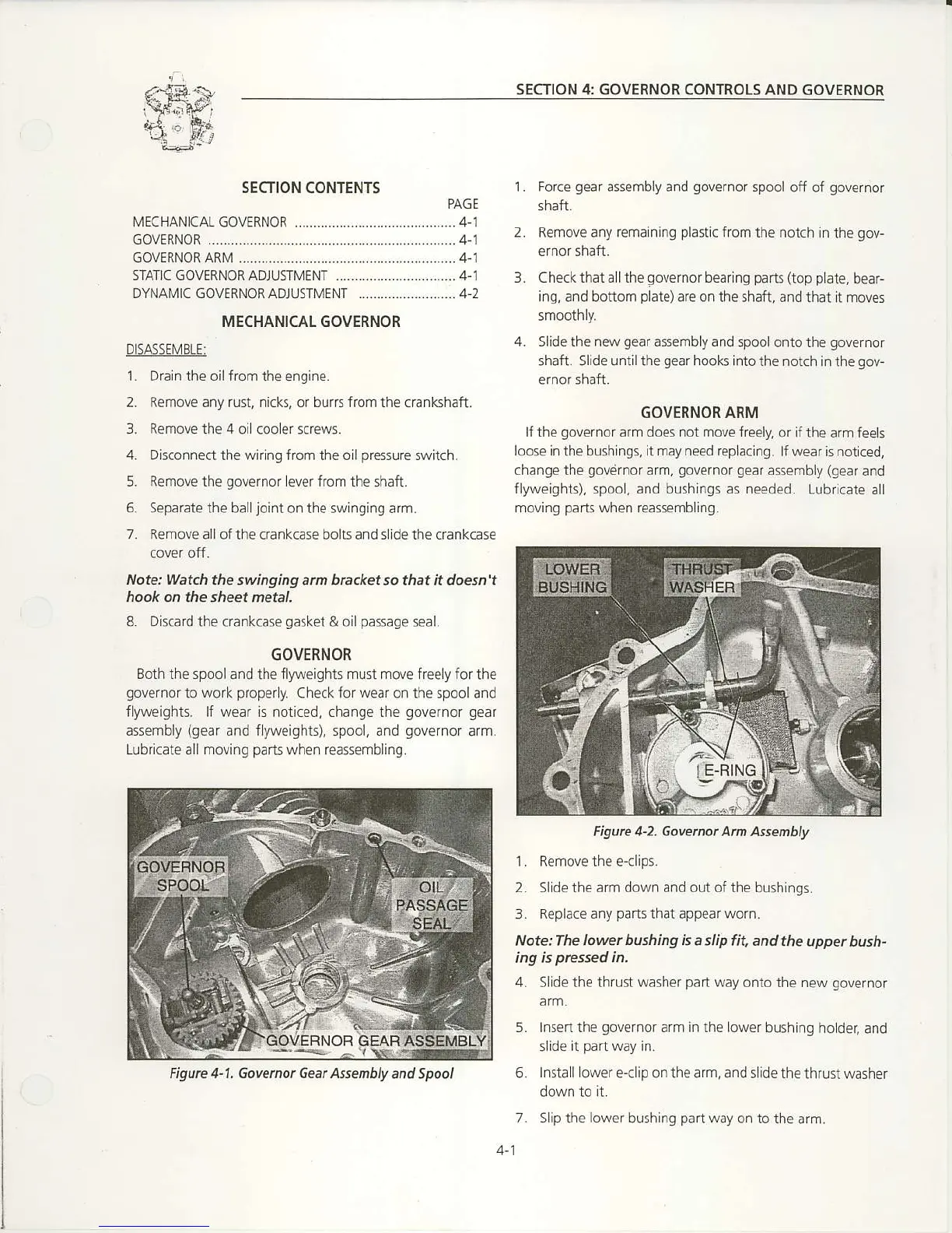
GOVERNOR
Eoth the
spooland the flyweiqhts
must move
freelyfor the
governor
to
work
properly.
Check
for
wear on the spool and
flyweights. lf wear is noiiced, change the
governor gear
assembly
(gear
and flyweights),
spool,
and
governor
arm.
Lub
cate all
moving
parts
when
reasserabling.
1. Force
gear
assembly and
governor
spool
off of
governor
shaft.
2. Remove any remainlng
plastic
from the notch in
the
gov-
ernor 5nan.
3. Checkthat allthe
governor
bearing
pans (top
pLile,
oear-
ing,
and bottom
plate)arc
ontheshafi, andthat
! moves
4. Slidethe newgear assemblyand
spoolontothe
governor
shaft. Sllde u
ntil
the
gear
hooks into the notch in
the
gov-
GOVERNOR ARM
lf the
governorarm
does not move frcely,
or ifthe arrn feeh
loose inthe
bushings,
itmay need
rcplacing. lf wea r is notlced,
change the
govdrnor
arm,
governor gear
assembly
(gear
and
flyweights), spool. and bushinqs as needed.
Lubricate all
moving
parts
when reassembling.
1. Remove the e-clips.
2. Sl d€ the arm down and out of the bushings.
3.
Replace any
parts
that appear worn,
Note: The lower
bushing is
a slip fit, and
the upper bush"
4.
Slide the
thrust washer
part
way
onto the new
governor
5. Insert the
governoa
arm in the lower
bushing hoder,
and
slid€
it
pair
way in.
6.
InstaLl
ower e-clip onthearm, ands ide the
thrust washer
7. Slip the lower
bushing
par!
way
on to the
afm.
Figure 4-2. Govenot Arm Assembly
Figure 4-1. Govemot Geat Assenbly
and Spool

 Loading...