SECTION
4:
GOVERNOR
CONTROLS
AND GOVERNOR
8. Slide the arm
in until the thrust washer is tight.
9. slidethelowerbushingdownand
intoitSholder,theninsirll
the upper e-clip.
ASSEMELE:
1. Clean any old
gasket
material from the crankcase
and
cover mating sudaces.
2.
Be sure thal the new oilpassage
o-ring is in
place.
3.
Put a
new
gasket
on the crankcase,
4. Slidethe
crankcase cover back on the crankcase.
Nol€:
Hold the
govemor
atm in
the counter-clo*wise
position
wlrile insta ing, Also, nldke
surc thatthe swing'
ing
an bhcket
goes
in
place.
5. Stan all of the crankcase
bolts, and then torque them to
35 ft.
lbs., following the
propertorque
sequence.
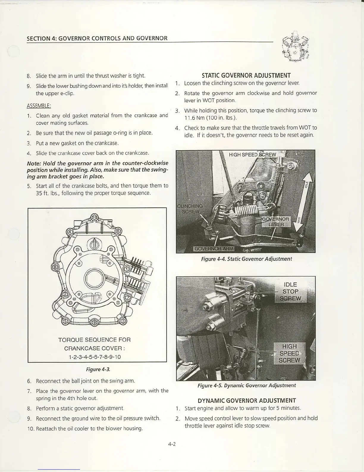
STATIC GOVERNOR ADIUSTMENT
Loosen the clinching
screw
on the
govemor
lever
Rotate
the
governor
arm clockwise and hold
governor
lever
in WOT
position.
While holding this
position,
torque the clinching screw to
11.6 Nm
(100
in.
Ibs.).
Check
to make sure that the throttle
travels from WOT to
idle.
lf it doesn't, the
governor
needs to be resetagain.
Figurc 4-5. Dynamic Govenor Adjustment
DYNAMIC GOVERNOR ADJUSTMENT
Slart engine and
a'bw 10 warr up fo 5 mi,rures.
Move speed
control lever to dowspeed
position
and hold
thrcttle
lever against idle nop scfew
1.
2.
L
TOROUE
SEQUENCE FOR
CRANKCASE
COVEF :
1
-2-3-4-5-6-7-8-9-
1
0
Figurc 4-3,
5. Reconnect the ball
joint
on the swinq arm.
7- Place the
govenor
lever on the
governor
arm,
with the
spring in the 4th hole out.
8.
Perform a static
governor
adjustment.
9. Reconnectthe
ground
wire to the oilpressu€
switch.
10. Reattach the oil cooler to
Ihe blower
housing
t.
2.
Figurc 4-4, Sati. Gowmot Adjustnent

 Loading...