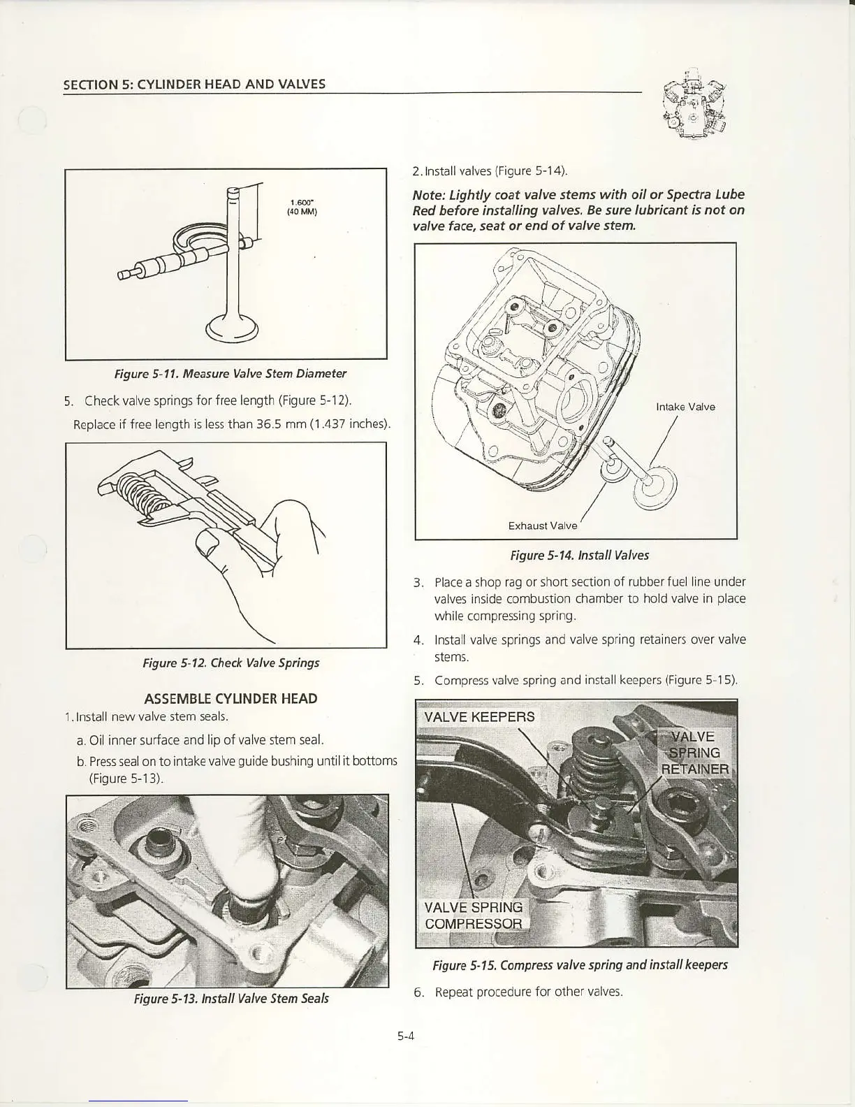
SECTION 5: CYLINDER
HEAD AND VALVES
2. nndllvalves
(Figure
5- 14).
Note: Lightly coat
valve stems with oil or Sped'a Lube
Red beforc insta ing
valves. Be surc lub cant is noton
valve fa.e, seat or
end of valve sten.
Figurc 5"11. Measurc Valve SteI,
Dianetel
5.
Check valve springs
for free lenqth
(Figure
5-12).
Replace lf
free length s ess than 36.5 mm
(1.437
lnchet.
Figurc 5-14. lnstall Valves
Place a shop
rag or shod section oi rubber fue ne under
valves
ins
de cornbustion
chamber to hod va ve in
place
while compressing
sp.ing.
lnna I va ve springs and
valve
sprinq
retalners
over
valve
Figure 5-12. Check Valve Spings
ASSEMBLE CYLINDER HEAD
l.lnstall newvalv€
stem seals.
a. Oi inner surface and
lip ofvi ve stem seal.
b.
Pressrealonto intake
va
lve
guide
bushing unlll
tbottoms
(Figure
513)
5. Compress
valve
sprlng
and instal keepeB
(Flgure
5 15).
Figurc 5-1 5. Conptess
valve spring and insta keeperc
6. Repeat
procedure
for oiher valves.
5-4
Figure 5-13, lnstall
valve Sten Seals

 Loading...