Installation
8 Automatic Transfer Switch Owner’s Manual
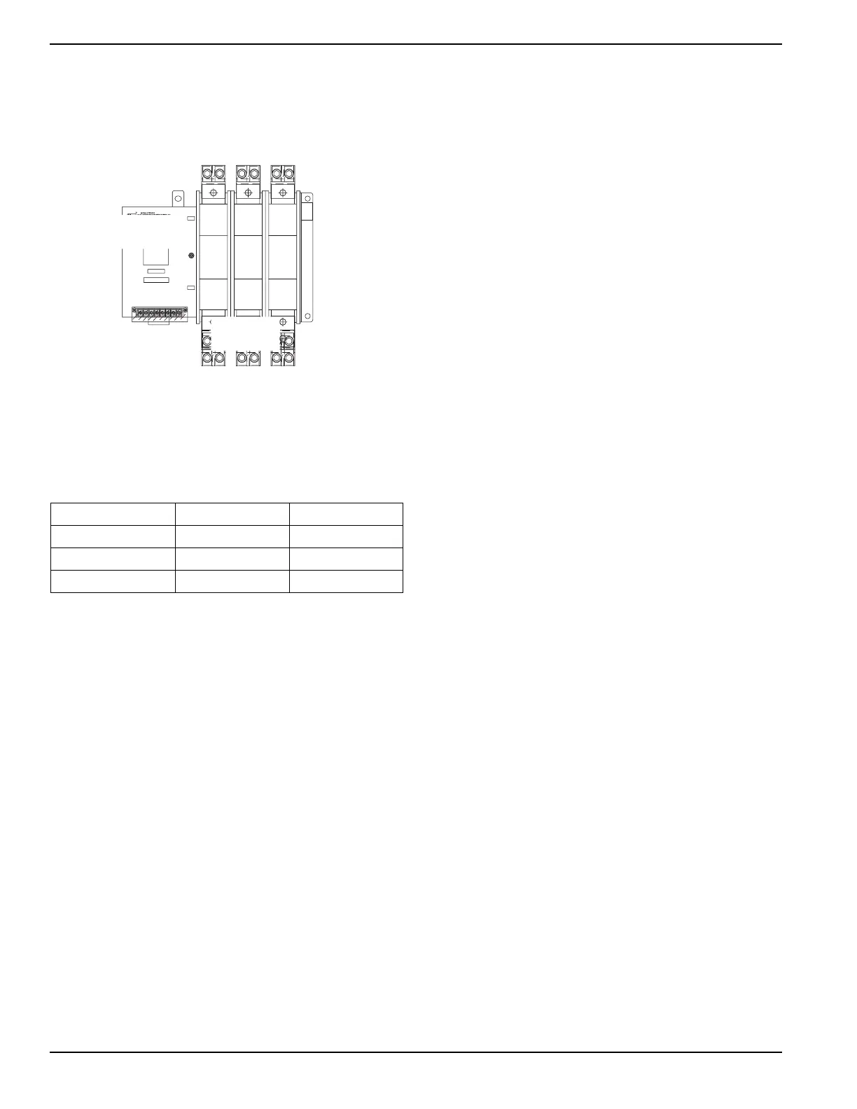
3.4.2— Transfer Mechanisms (600-2600A)
See Figure 3-2. The transfer mechanism may be either a
2-pole, 3-pole, or 4-pole type. The switch enclosure may
include a neutral block for connection of the neutral line.
Figure 3-2. Transfer Mechanism
Before connecting wiring cables to terminals, remove any
surface oxides from the cable ends with wire brush. If
aluminum conductors are used, apply joint compound.
Tighten terminal lugs to the torque values in the following
chart.
All power cables should enter the switch next to transfer
mechanism terminals. Standard terminal lugs on the
transfer mechanism are solderless, screw-type.
Be sure to maintain proper electrical clearance between
live metal parts and grounded metal. Allow at least one
inch for circuits over 400 amps.
3.5 — Transfer Mechanism
The transfer mechanism houses the main, current carry-
ing contacts, along with other mechanical and electrical
components, required for operating the switch. The main
contacts are electrically operated and mechanically
latched in place. See Figure 3-1.
Power for the operating coils is taken from the source of
supply that the Customer Load is being transferred to.
Therefore, transfer to any power source cannot occur
unless that power source is available to the switch.
3.5.1— 100-400A Models
Main contacts are actuated by a single solenoid, are
electrically operated and mechanically held. load or “T”
contacts, bolted to an insulated plastic pole piece are sta-
tionary. The normal (utility) and standby (emergency)
contacts are moveable. The contacts are actuated by
means of a closing coil and mechanical linkage. The pole
assemblies which retain the stationary moveable main
contacts are assembled together and retained by through
bolts.
3.5.2— 600-2600A Models
600-2600A models are bolted to an insulated plastic pole
piece and are stationary. The utility (normal) and genera-
tor (emergency) contacts are moveable.
3.6 — Transfer Mechanism Operation
3.6.1— 100-400A Models
There is a single solenoid coil in the "W" switch that is
used to transfer the power to the respective load. The
solenoid coil is energized to move the mechanism to the
neutral position (both sources of supply disconnected). If
the solenoid coil is kept energized the switch mechanism
will remain in the neutral position. When the solenoid coil
is de-energized the mechanism will close the contacts in
the opposite position. This process is repeated to move
the mechanism back to the original position.
3.6.2— 600-2600A Models
There are three (3) coils inside a “WN” switch that are
used in transferring power to the respective load;
• Closing Coil - When energized, closes the main
contacts on Utility or Generator side, depending on
if the select coil is energized or not.
• Select Coil - When energized, the mechanism is
configured to close the Generator supply contacts
when the closing coil is energized.
• Trip Coil - When energized, the main contact latch
is released and the contacts move to the open
position by spring tension.
All 3 solenoids are only energized momentarily.
Refer to the diagnostic repair manual 079247, section 9.6
for complete operational analysis.
Switch Rating Wire Size Torque
600 AMP 500MCM-1/0
375
in-lbs
800/1000 AMP 500MCM-1/0
375
in-lbs
1200/2600 AMP 750MCM-1/0
500
in-lbs

 Loading...


