Operation
16 Automatic Transfer Switch Owner’s Manual
transfer switch by whatever means provided (such
as the main line circuit breaker), then return to Step
1 of Subsection 4.3 — Voltage Checks.
7. On the enclosure door, check that the utility avail-
able LED is ON.
8. With an accurate AC voltmeter, check the phase-
to- phase (line-to-line) and phase-to-neutral (line-
to- neutral) voltages present at transfer mechanism
terminals N1, N2, and N3, and neutral. supplied
voltages must be fully compatible with transfer
switch rated voltage.
IMPORTANT: Verify the phase rotation of normal (utility)
power lines and transfer switch load power lines are com-
patible.
9. Refer to the standby generator instruction manual.
Make sure the generator engine has been properly
serviced and prepared for use, as outlined in that
manual. Then start the generator engine manually.
Let the engine stabilize and warm up for a few min-
utes.
10. Turn ON the standby (emergency) power supply to
the transfer switch by whatever means provided
(such as the main line circuit breaker).
11. With the generator running, check that the standby
- operating LED on the switch enclosure door is
ON.
12. With an accurate AC voltmeter, check phase-to
phase (line-to-line) and phase-to neutral (line-to
neutral) voltages present at transfer mechanism
terminals E1, E2 and E3. Also check AC frequency
at those terminals. Generator AC output voltage
and frequency must be compatible with transfer
switch rated voltage and frequency.
IMPORTANT: Verify the phase rotation of standby (genera-
tor) power lines and transfer switch normal (utility) and
load power lines are compatible.
13. If supplied voltage or frequency is incorrect, refer to
standby generator Owner’s Manual. If AC fre-
quency is incorrect, adjust engine governed speed.
If voltage is incorrect, adjust generator’s voltage
regulator or correct the problem.
14. When supplied voltage and frequency is correct,
shut down the engine manually.
IMPORTANT: Supplied voltages from both normal (utility)
and standby (emergency) power sources must be compati-
ble with transfer switch rated voltage before proceeding.
15. Connect the transfer switch load to the transfer
switch after completion of Subsection 4.3 — Volt-
age Checks. Connect the load to the transfer
switch by whatever means provided, such as cir-
cuit breaker(s), then proceed to Subsection 4.4 —
Electrical Operation.
4.4 — Electrical Operation
Test transfer system electrical operation as follows:
1. On the enclosure door, check that the utility avail-
able led is ON.
2. On the enclosure door, check that the switch posi-
tion-utility LED is ON.
IMPORTANT: The utility available LED and the switch posi-
tion-utility LED (on enclosure door) must both be ON
before proceeding to Step 3.
3. Refer to the appropriate owner’s manual. Be sure
the standby generator is prepared for automatic
operation.
4. In the switch enclosure, set the Maintenance Dis-
connect switch to AUTOMATIC.
5. Press the “TEST” button on the enclosure door.
Generator startup and transfer to the standby
power source should occur. Refer to the
“Sequence of Operation” section.
6. Press the “TEST” button again to initiate the
retransfer sequence. The customer load will be
transferred back to the utility power source, using
the preset times. The generator will shut down
once the engine cool down timer has expired.
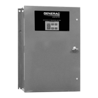
4.5 — Switches and Indicators
This section will familiarize the reader with switches and
indicators on the membrane switch panel mounted on the
enclosure door, as well as the Maintenance Disconnect
switch inside the switch enclosure. See Figure 4-7.
Figure 4-7. OTTS Switch
48*5$)
104*5*0/
(&/&3"503 65*-*5:
45"/%#:
01&3"5*/(
65*-*5:
"7"*-"#-&
4:45&.
3&"%:
3&563/
50
/03."-
5&45
'"45
5&45
3&4&5
 Loading...
