Installation
Automatic Transfer Switch Owner’s Manual 11
3.11.6— Voltage Limits
Determination of proper Utility is performed by the H or G
controller against user programmable limits. If the com-
munication link to the transfer switch breaks down, the
following criteria are used for a local determination.
Dropout — any phase outside - 70 to +130% of nomi-
nal (not the average voltage)
Pickup — all phases > +75% of nominal
3.12 — Programming
The HTS transfer switch is controlled by the G/H control
panel on the engine generator. The timer, voltage pickup,
dropout and exercise settings are programmed into the
G/H control panel. Please refer to the G/H control panel
manual for details on programming the HTS transfer
switch controls.
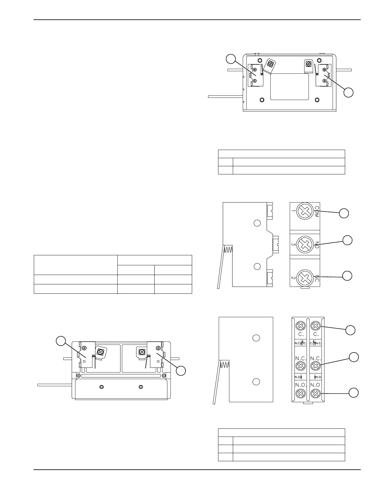
3.13 — Auxiliary Contacts
It is possible to add Auxiliary Contacts on the transfer
switch to operate customer accessories, remote advisory
lights, or remote annunciator devices. It is necessary to
change the single pole limit switch to a double pole
device. Reconnect 0A, 147 and 148 to like terminals on
the double limit switch. A suitable power source must be
connected to the common (C) terminal.
Contact operation is shown in the following chart:
NOTE: Auxiliary Contacts are rated 10 amps at 125 or 250 volts
AC. do not exceed the rated voltage and current of the contacts.
Figure 3-6. 100-200 amp Switches
Figure 3-7. 300-2600 amp Switches
Figure 3-8. Single Auxiliary Contacts
Figure 3-9. Double Auxiliary Contacts
Switch Position
Utility Standby
Common to Normally Open Closed Open
Common to Normally Closed Open Closed
Figure 3.6 – 3.7
A Auxiliary Contact (Actuated)
B Auxiliary Contact (Non-Actuated)
Both side views shown in UTILITY position.
Figure 3.8 – 3.9
ACommon
B Normally Open
C Normally Closed

 Loading...


