Operation
20 Automatic Transfer Switch Owner’s Manual
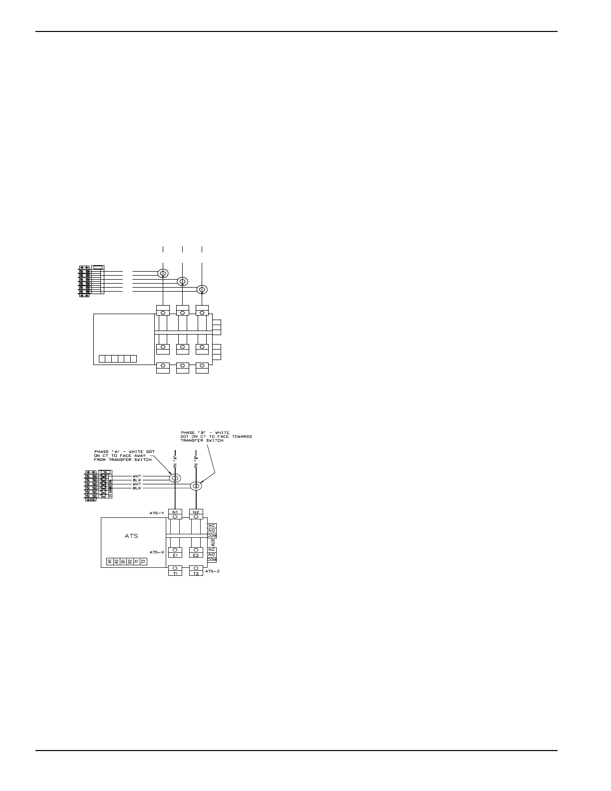
4.7.2— Instrument Package (Utility Monitor)
This option is used to measure the Utility source current
that is coming to the transfer switch. The instrument
package includes a terminal strip used to connect the
current transformers and associated wiring. The HTS
controller takes in the current signals and passes them
on to the Hxxx or Gxxx panel for display on a PC through
GenLink-DCP.
Route the Utility Supply cables through the center of the
current transformers. Connect the signal wires of the cur-
rent transformers to terminal strip (TB1-1). See Figure 4-
9 for three-phase connection details. See Figure 4-10 for
single-phase connection details.
Figure 4-9. Connect Signal Wires
(Three-Phase)
Figure 4-10. Connect Signal Wires
(Single-Phase)
!43
!58
",+
7(4
",+
7(4
",+
7(4
#4#/..%#4)/.
0.&
0(!
0(!
0("
0("
0(#
0(#
4"
!
"
!
"
4
4
!43 8
4
%
4
%
!43 9
. .
!43 :
4
%
#/-
./
.#
#/-
./
.
.#
4
7(4
",+
",+
7(4
7(4
",+
0(!
0(#
0("
./4%7()4%$/4/.#4
4/&!#%!7!9&2/-
42!.3&%237)4#(

 Loading...


