Installation
Automatic Transfer Switch Owner’s Manual 9
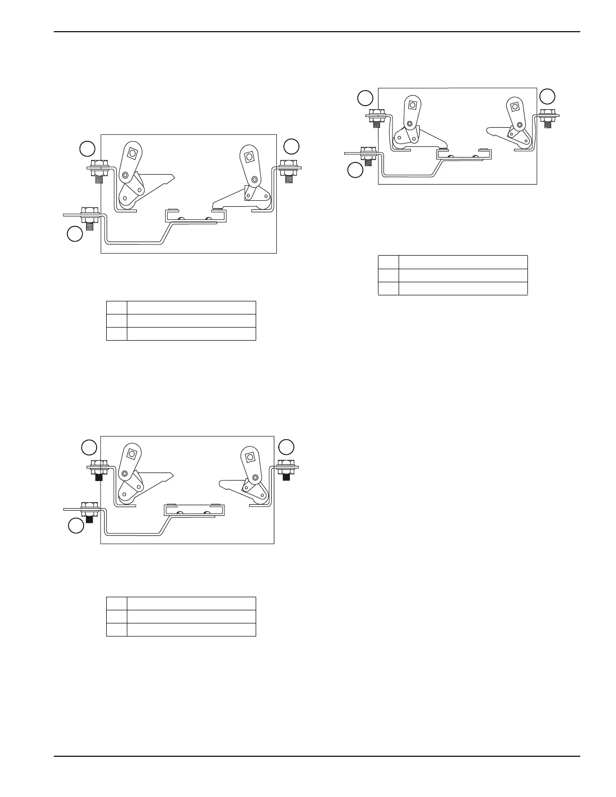
3.7 — Main Contacts at Normal (Util-
ity)
The illustration shows the load terminals connected to
the normal (utility) terminals. Window “A” will display the
word “ON,” Window “B” the word “OFF.” See Figure 3-3.
Figure 3-3. Main Contact at Normal (Utility)
3.8 — Main Contacts at Neutral
Load terminals are disconnected from both power supply
terminals. The word “OFF” will be displayed in both Win-
dows “A” and “B.” See Figure 3-4.
Figure 3-4. Main Contacts at Neutral
3.9 — Main Contacts at Standby
(Emergency)
Load terminals are connected to the standby (emer-
gency) power supply. Window “B” will display the word
“ON,” Window “A” the word “OFF.” See Figure 3-5.
Figure 3-5. Main Contacts at Standby
(Emergency)
3.10 — Connecting Controller Com-
munication Wires
Use shielded 2-wire communications cable (such as
Belden #9460) to make the communications line connec-
tion from the HTS transfer switch to the engine generator
connection panel. This cable is to be routed in a separate
conduit between the HTS transfer switch and the engine
generator. The cable is to be connected as follows:
• HTS transfer switch - 6-position terminal block, in
the bottom of the transfer switch enclosure (labeled
“comm. Ports”).
• Engine generator - terminal strip in customer con-
nection panel. Do not connect the shield at this
end.
3.11 — Setting Dip Switches
The dip switches, in the HTS, are read once, only at
power up. If the communications to the Power Manager
or the engine controller are working, it will overwrite the
dip switch settings. In this way there are no conflicts and
also the transfer switch will use the latest settings even if
the communications fail.
A Utility Position “ON”
B Emergency Position “OFF”
CLoad
A Utility Position “ON”
B Emergency Position “OFF”
CLoad
A Utility Position “ON”
B Emergency Position “OFF”
CLoad

 Loading...


