Operation
14 Automatic Transfer Switch Owner’s Manual
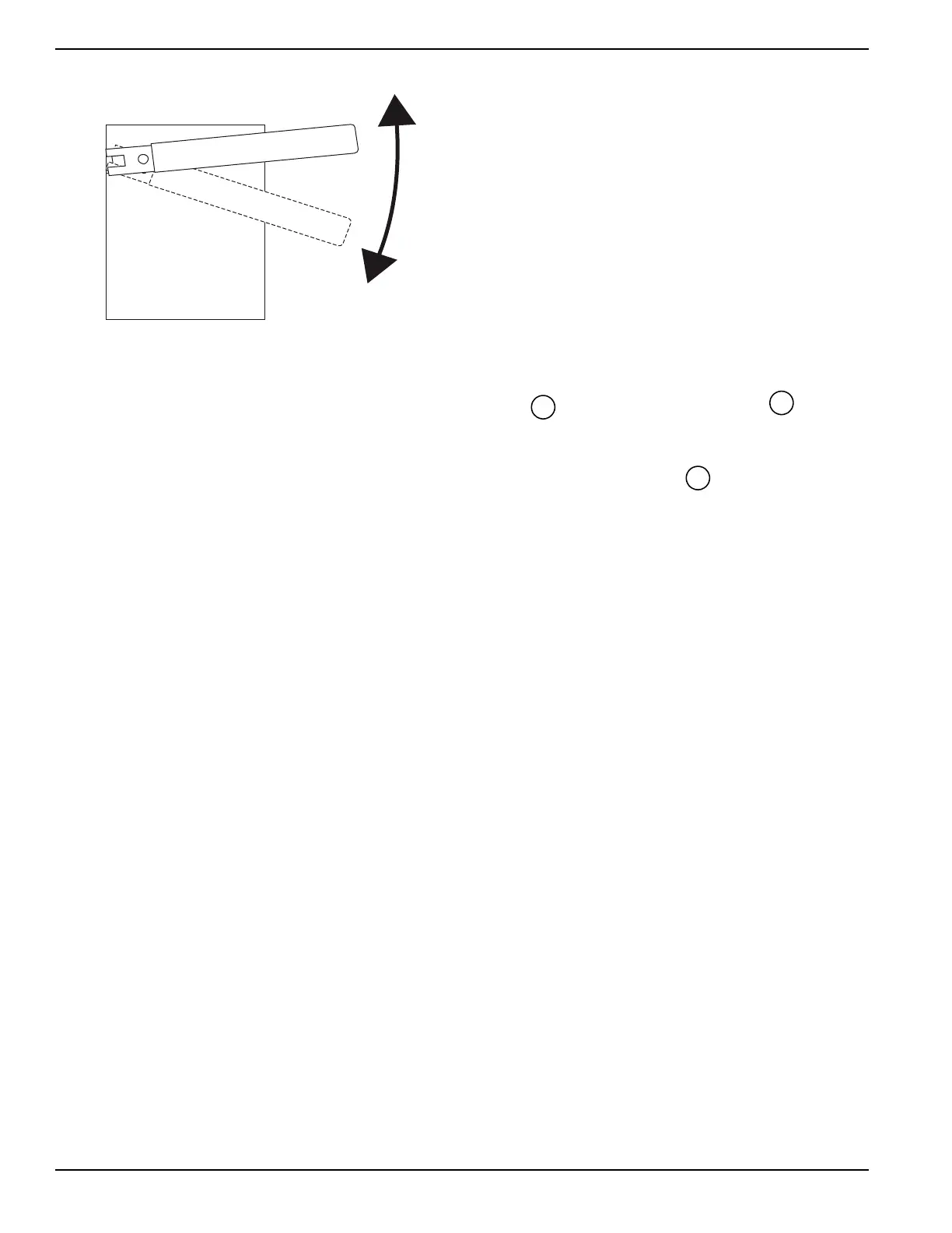
Figure 4-3. Move Handle Down
4.2.1— 100 - 400 Amp Models
4.2.1.1—Close to Normal Source Side
Before proceeding, verify the position of the switch by
observing window “A” in Figure 4-1. If window “A” reads
“ON”, proceed with Step 1, and if it reads “OFF,” proceed
with Step 2.
1. With the handle attached to the actuating shaft,
move handle in the direction of the arrow on the
switch cover until it stops — do not force. Release
handle slowly to allow the spring in the switch box
to relax. “OFF” now appears in Window “A” and
“ON” appears in Window “B”. Proceed with Step 2.
2. With the handle attached to the actuating shaft,
move handle in the direction of the arrow on the
switch cover until it stops — do not force. Release
handle slowly to allow the spring in the switch box
to relax. “ON” now appears in Window “A” and
“OFF” appears in Window “B”. Proceed with Sub-
section 4.2.1.2— Close to Standby Source Side.
4.2.1.2—Close to Standby Source Side
Before proceeding, ensure completion of Step 2 under
Subsection 4.2.1.1— Close to Normal Source Side. See
Figure 4-1. This will ensure that Window “B” on the
switch reads “OFF.” With the handle attached to the actu-
ating shaft, move the handle in the direction of the arrow
on the switch cover until it stops - do not force. Release
handle slowly to allow the spring in the switch box to
relax. “OFF” now appears in Window “A” and “ON”
appears in Window “B”.
4.2.1.3—Return to Normal Source Side
Manually actuate switch to return Window “A” to the “ON”
position.
4.2.2— 600 - 2600 Amp Models
4.2.2.1—Trip to Neutral Position
1. See Figure 4-4. Remove manual handle from
square shaft at the upper left corner of the switch.
2. Insert a screwdriver into the “Trip” hole and push
in.
3. The main contact should trip to the neutral position
and the word “OFF” should appear in both windows
“A” and “B”.
Figure 4-4. Trip to Neutral
4.2.2.2—Close to Emergency Source Side
Before proceeding, verify the position of the switch by
observing window “A” and window “B”. If window “B” dis-
plays ON, the ATS is closed in the standby position, with
the load connected to the standby source. It is not neces-
sary to manually close in the standby position. See Fig-
ure 4-5.
If window “B” reads OFF and window “A” reads ON it will
be necessary to trip the ATS to the neutral position. See
the Trip to Neutral Position section.
With handle attached to the actuating shaft. Insert screw-
driver into hole marked “Select”. While pushing inward on
screwdriver, move manual handle upward as indicated by
arrow in illustration until it stops. do not force. Confirm
main contacts close to standby source when window “B”
is ON and window “A” is OFF. Remove handle from
switch.
1. See Figure 4-5. Attach manual handle to shaft “M.”
2. Insert screwdriver into the “Select” hole and push
in.
3. While pushing screwdriver in, actuate handle in
direction indicated by arrow.
4. Confirm closure to emergency source by the word
“OFF” in Window “A,” “ON” in Window “B.”

 Loading...


