Generac
®
Power Systems, Inc. 9
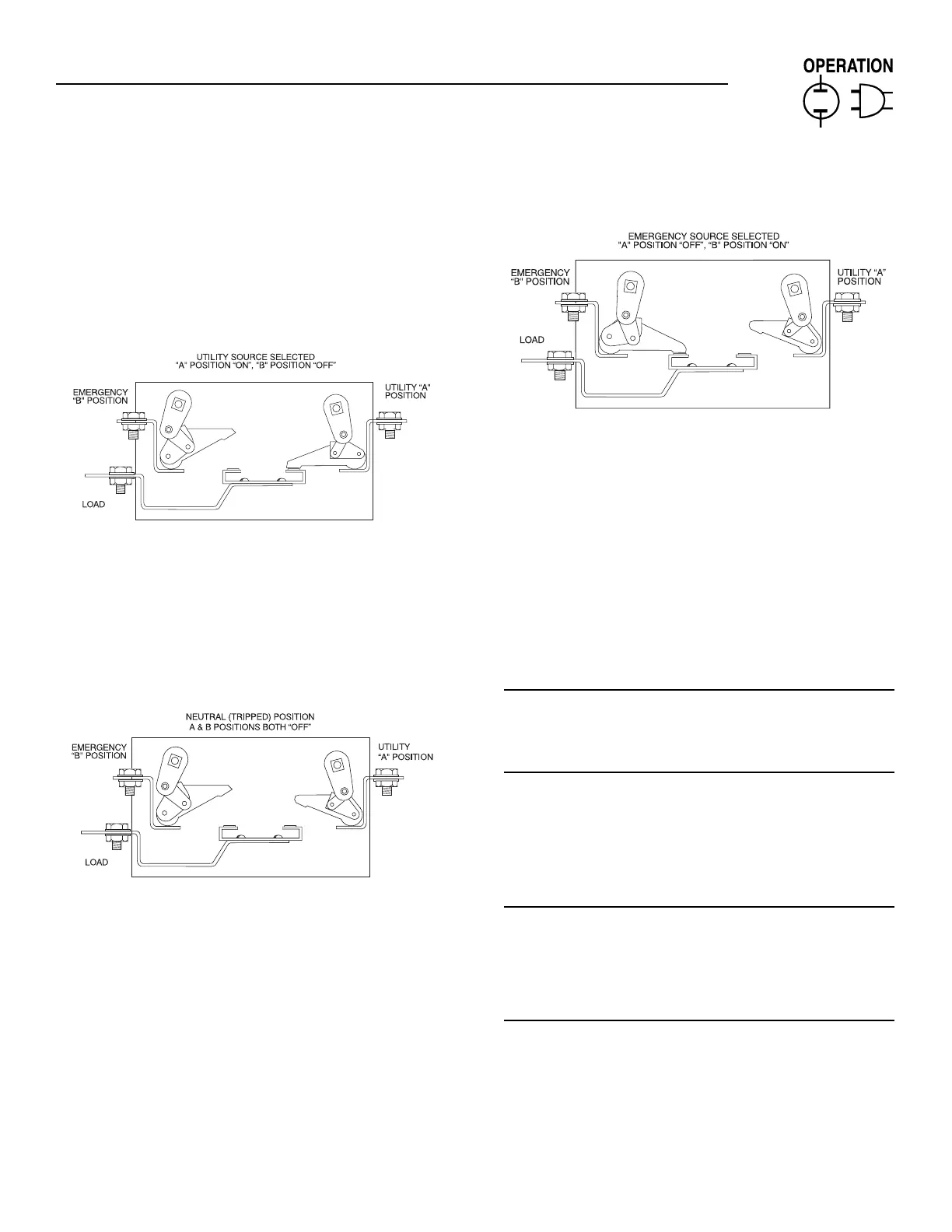
3.5 MAIN CONTACTS AT NORMAL
(UTILITY)
The illustration shows the LOAD terminals connect-
ed to the NORMAL (UTILITY) terminals. window “A”
will display the word “ON”; Window “B” the word
“OFF” (Figure 3.2).
Figure 3.2 — Main Contact at Normal (Utility)
3.6 MAIN CONTACTS AT NEUTRAL
LOAD terminals are disconnected from both power
supply terminals. The word “OFF” will be displayed
in both Windows “A” and “B” (Figure 3.3). This occurs
when the solenoid coil is kept energized.
Figure 3.3 — Main Contacts at Neutral
3.7 MAIN CONTACTS AT STANDBY
(EMERGENCY)
LOAD terminals are connected to the standby
(EMERGENCY) power supply. Window “B” will dis-
play the word “ON”; Window “A” the word “OFF”
(Figure 3.4).
Figure 3.4 — Main Contacts at Standby
(Emergency)
3.8 SWITCHES AND ADVISORY LAMPS
This section will familiarize personnel with switches
and advisory lights on the transfer switch enclosure
door, as well as with the Safety Disconnect Switch
inside the switch enclosure.
Circuit board inside the switch door may also mount
several switches. Operation of these switches is cov-
ered in the section entitled SENSOR AND TIMER
ADJUSTMENTS.
3.9 SOURCE AVAILABLE LED
3.9.1 UTILITY
This LED will go ON when the UTILITY (NORMAL)
supply voltage is available to the transfer switch.
3.9.2 GENERATOR
This LED will go ON when the GENERATOR
(STANDBY) supply voltage is available to the transfer
switch.
3.10 SWITCH POSITION LED
3.10.1 CLOSED TO GENERATOR
This LED will go ON when main current carrying con-
tacts have actuated to their STANDBY (GENERATOR)
position and that power source is available to the
transfer switch (Figure 3.5).
3.10.2 CLOSED TO UTILITY
This LED will go ON when main contacts have actu-
ated to NORMAL (UTILITY) position and that power
supply is available to the transfer switch.
◆
◆
Section 3 — Operation
Generac ILC Type Transfer Switch
 Loading...