Generac
®
Power Systems, Inc. 3
1.2.2.6 REMOTE ALARM CONTACTS
Each TVSS module is equipped with a set of alarm
contacts. These alarm contacts are wired to a two-
position terminal strip adjacent to the TVSS module.
The internal contacts are normally closed to indicate
normal operation. If one of the protection elements
become damaged, the contacts will open, indicating
the failure.
Contacts are rated 2A @ 125 VAC.
1.2.3 AUTOMATIC TRANSFER SWITCH
The automatic transfer switch is used for transfer-
ring critical electrical load from a NORMAL (UTILI-
TY) power source to a STANDBY (EMERGENCY)
power source. Such a transfer of electrical loads
occurs electrically when initiated by the operator. The
transfer switch prevents electrical feedback between
two different power sources (such as the NORMAL
and STANDBY sources) and, for that reason, codes
require it in all standby electric system installations.
The transfer switch consists of a transfer mechanism
and an operator panel.
1.2.4 PANEL BOARD
This unit is provided with a 42 position panel board
(manufactured by Siemens) for mounting of individ-
ual branch circuit breakers. Single phase ILC's are
equipped with a single phase panel board. Three
phase ILC's are equipped with a three phase panel
board. It is factory wired and the customer connec-
tion is made here.
1.2.4.1 Voltage Rating
• 240 Volt maximum when used with BL, BLH, and
QJH2 branch circuit breakers.
1.2.4.2 Amperage Rating
The panel interior has been tested to 250 amps, how-
ever is limited to 200 amp in this application. The
limitation comes from the service disconnect circuit
breakers ratings.
1.2.4.3 Recommended Circuit Breakers
• Only circuit breakers manufactured by Siemens
Energy & Automation, Inc.
• This panel board is UL component recognized only
when used with Siemens type BL, BLH, or QJH2
and at a suitable current rating for the branch circuit.
• Blank covers must be installed in all open spaces
(no circuit breaker installed), before putting the
system in service. Use ONLY Siemens catalog num-
ber QF-3.
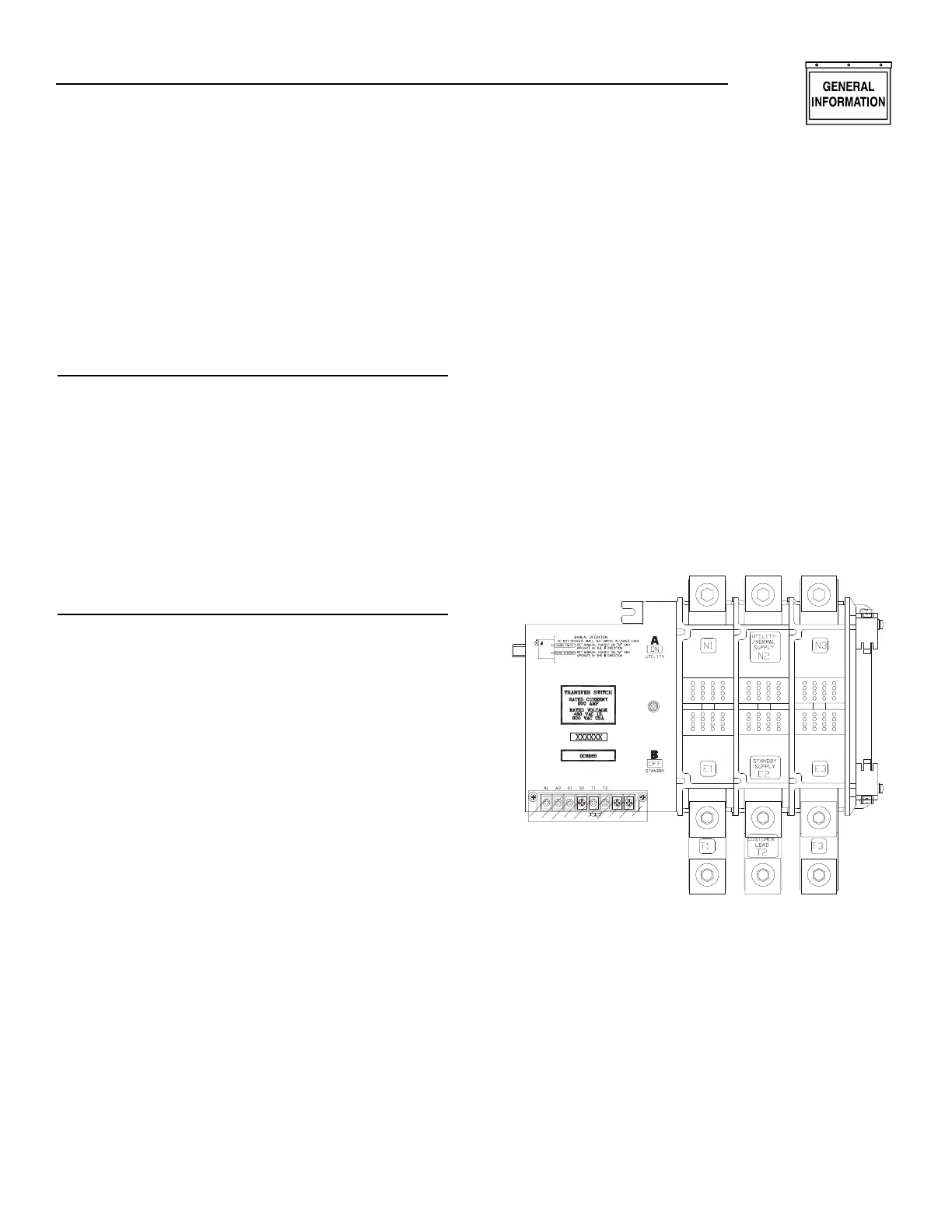
1.3 TRANSFER MECHANISM
• The transfer mechanism houses the main, current
carrying contacts, along with other mechanical and
electrical components required for operating the
switch (Figure 1.1). Main contacts are actuated by
a single solenoid, are electrically operated and
mechanically held. Power for that coil’s operation
is taken from the side to which the LOAD is being
transferred. Therefore, transfer to any power
source cannot occur unless that power source is
available to the switch.
• LOAD (or “T”) contacts are bolted to an insulated
plastic pole piece and are stationary. The NORMAL
(UTILITY) and STANDBY (EMERGENCY) contacts
are moveable. The contacts are actuated by means
of a closing coil and mechanical linkage. The pole
assemblies which retain the stationary moveable
main contacts are assembled together and retained
by through-bolts. Either 2, 3 or 4-pole assemblies
may be used to form a 2, 3 or 4-pole mechanism.
Figure 1.1 — The Transfer Mechanism
1.4 RATINGS — DATA PLATE
This ILC is rated 200 amp at 120/240 or 120/208
VAC single phase or 120/208 VAC three phase. A
DATA PLATE is permanently affixed to the transfer
switch subplate. Use this ILC only within the specific
limits shown on the DATA PLATE and the application
decal located on the inside lower left side of the cab-
inet.
When requesting information or ordering parts for
this equipment, make sure to include all information
from the DATA PLATE. Record the Model and Serial
numbers in the space provided on the top of page 4
for future reference.
✧ ✧ ✧
✧
Section 1 — General Information
Generac ILC Type Transfer Switch
 Loading...