Generac
®
Power Systems, Inc. 5
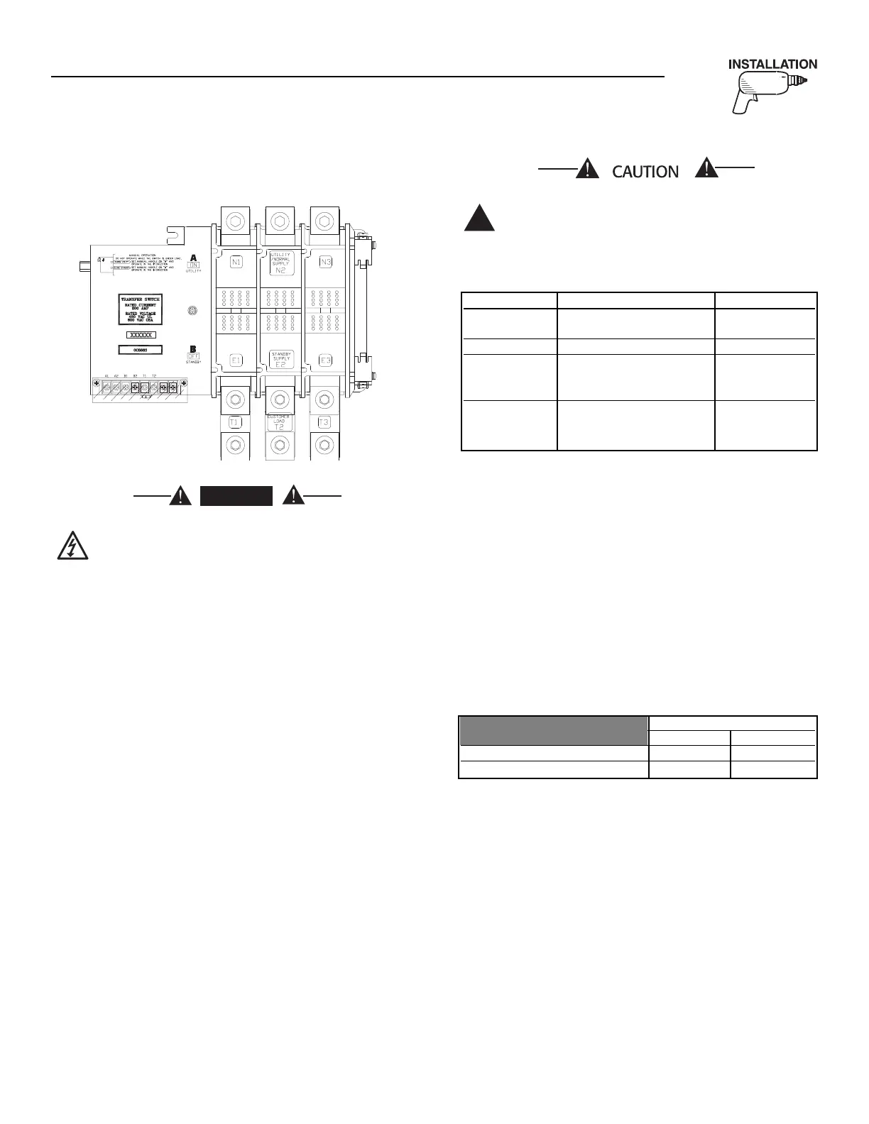
Figure 2.1 — Typical 3-Pole Transfer Mechanism
(200 Amp Shown)
All power voltage supplies must be turned off
before connecting to the power source and
load lines. Failure to turn off power voltage
supplies will result in extremely dangerous
and possibly lethal electrical shock.
All power cables should enter the switch next to the
service disconnect circuit breaker terminals.
Standard terminal lugs on the service disconnect are
solderless, screw-type.
Connect power source and load conductors to clear-
ly marked terminal lugs on the ILC as follows:
• LOAD leads: Connect to individual branch circuit
breaker terminals.
• NORMAL (UTILITY) Source Leads: Connect to
service disconnect circuit breaker.
• STANDBY (EMERGENCY) Source Leads: Connect
to service disconnect circuit breaker.
Conductor sizes must be adequate to handle the max-
imum current to which they will be subjected, based
on the 75°C column of tables, charts, etc. used to size
conductors. The installation must comply fully with
all applicable codes, standards and regulations.
Before connecting wiring cables to terminals, remove
any surface oxides from the cable ends with a wire
brush. If ALUMINUM conductors are used, apply cor-
rosion inhibitor to conductors. After tightening ter-
minal lugs, carefully wipe away any excess corrosion
inhibitor.
Tighten terminal lugs to the torque values as noted
inside the transfer switch door.
Use a torque wrench to tighten the conduc-
tors, being sure not to overtighten, or dam-
age to the switch base could occur. If not
tightened enough, a loose connection would
result, causing excess heat which could dam-
age the switch base.
Be sure to maintain proper electrical clearance
between live metal parts and grounded metal. Allow
at least 1/2 inch for 100-400 amp circuits.
2.5 AUXILIARY CONTACTS
There is access to Auxiliary Contacts on the transfer
switch to operate customer accessories, remote advi-
sory lights, or remote annunciator devices. A suitable
power source must be connected to the COMMON (C)
terminal. The contacts shown as FACTORY in Figure
2.2 (at the top of page 5), are connected at the facto-
ry for operating transfer switch advisory lights. The
contacts shown as auxiliary are available for cus-
tomer use.
Contact operation is shown in the following chart:
NOTE:
Auxiliary Contacts are rated 10 amps at 125 or
250 volts AC. DO NOT EXCEED THE RATED
VOLTAGE AND CURRENT OF THE CONTACTS.
 Loading...