2 Generac
®
Power Systems, Inc.
Section 1 — General Information
Generac ILC Type Transfer Switch
1.1 INTRODUCTION
This manual has been prepared especially for the
purpose of familiarizing personnel with the design,
application, installation, operation and servicing of
the applicable equipment. Read the manual careful-
ly and comply with all instructions. This will help to
prevent accidents or damage to equipment that might
otherwise be caused by carelessness, incorrect appli-
cation, or improper procedures.
Every effort has been expended to make sure that the
contents of this manual are both accurate and cur-
rent. Generac, however, reserves the right to change,
alter or otherwise improve the product at any time
without prior notice.
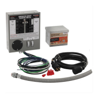
1.2 EQUIPMENT DESCRIPTION
This Integrated Load Center (ILC) is a combination of
individual components that perform four basic func-
tions.
1.2.1 SERVICE DISCONNECT
This unit is equipped with a 200 amp circuit break-
er for each source of supply, UTILITY and GENERA-
TOR. This circuit breaker can serve as the service
disconnect for each of the supplies.
1.2.2 TRANSIENT VOLTAGE SURGE
SUPPRESSION
The Transient Voltage Surge Suppression (TVSS) is
provided to protect the load from electrical surges
and/or transient voltage spikes. This device is physi-
cally located next to the service disconnect circuit
breakers and electrically connected to the load side
of the service disconnect. A TVSS module is standard
and protects the utility supply; the generator supply
TVSS protection is provided in some models. A 30
amp circuit breaker is provided to disconnect the
TVSS from the live ILC for maintenance or replace-
ment.
The TVSS is made up of multiple solid state Metal
Oxide Varistors (MOV) connected in parallel for each
mode of protection. These devices are equipped with
integrated short circuit and individual component
level fusing. They are self-resetting and fully automat-
ic.
1.2.2.1 Modes of Protection
The TVSS provides protection on all modes:
• Single Phase (6) - L-L, L-N, L-N, L-G, L-G and N-G.
• Three Phase (10) - L-L, L-L, L-L, L-N, L-N, L-N,
L-G, L-G, L-G and N-G.
1.2.2.2 Ratings
• Surge Capacity: 88 kA per mode.
• Suppression Level (typical):
L-N = 330 V
L-G = 400 V
N-G = 400V
L-L = 700 V
1.2.2.3 Certification
The TVSS is UL recognized to the requirements of UL
1449 2nd edition.
1.2.2.4 TVSS Disconnect
Each TVSS is provided with a disconnect. The dis-
connect is a 30 amp circuit breaker, 2-pole for single
phase and 3-pole for three phase. This is to allow
replacement of the TVSS module without interrup-
tion of the electrical supply to the load.
REPLACEMENT OF THE TVSS MODULE WHILE
THE ATS - ILC IS ENERGIZED SHOULD ONLY BE
PERFORMED BY A QUALIFIED ELECTRICIAN.
BE SURE TO TURN ON TVSS DISCONNECT CIR-
CUIT BREAKER WHEN THE PROCEDURE IS COM-
PLETE. IF THE CIRCUIT BREAKER IS NOT TURNED
ON THE TVSS MODULE WILL NOT PROVIDE ANY
SURGE PROTECTION FOR THE CUSTOMER
LOAD.
1.2.2.5 STATUS INDICATORS
Each TVSS module is equipped with a set of LED
indicators that are on the cover of the individual
module. The LED's are connected internally to indi-
cate that the mode of protection is in working order
and providing the indicated mode of protection. The
LED's are on when the mode of protection is available
and the power source is also available. For the power
source to be available, the associated service discon-
nect circuit breaker must be ON, the associated
TVSS disconnect circuit breaker must be ON and the
associated source must be present.
The LED status indicators can be viewed from the
outside of the enclosure or directly on the TVSS mod-
ule with the enclosure door open. All four (4) LED's
(single phase) or all six (6) LED's (three phase)
should be on to indicate the TVSS module is ready to
provide protection against surge voltages.
✧
 Loading...