Generac
®
Power Systems, Inc. 7
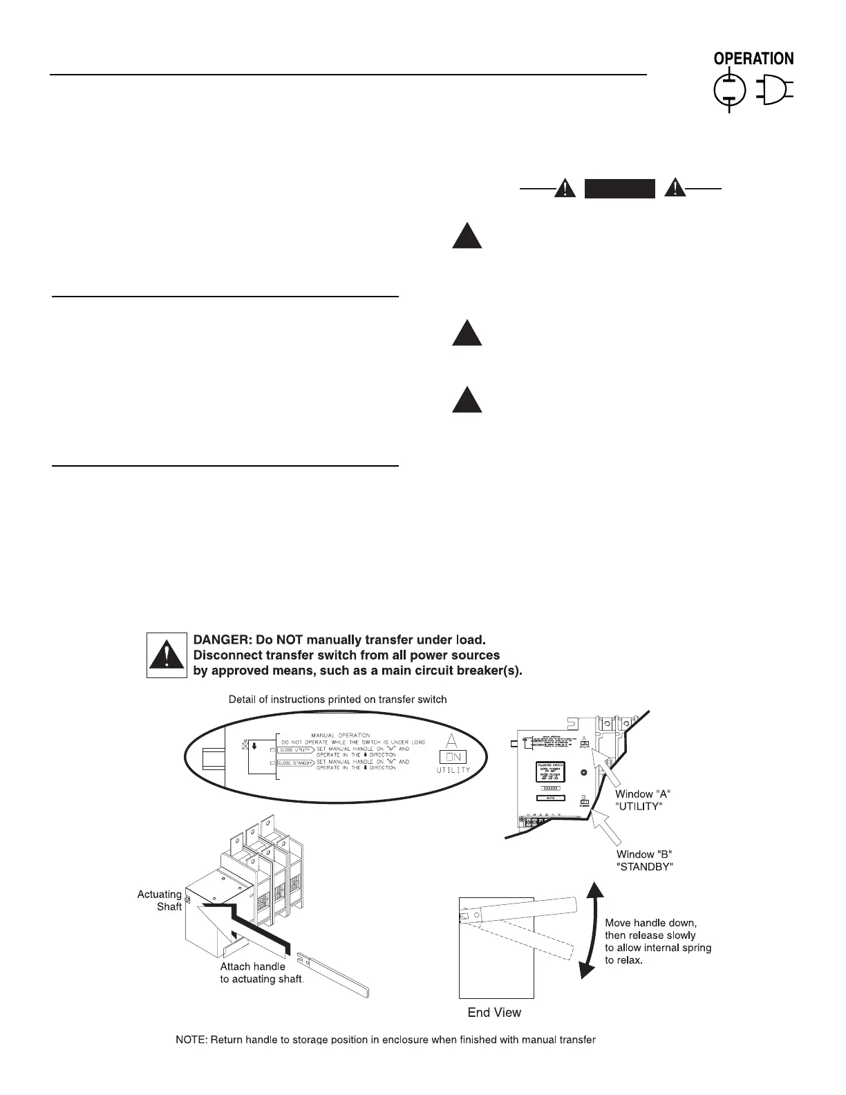
Step 2: With the handle attached to the actuating
shaft, move handle in the direction of the
arrow on the switch cover until it stops — DO
NOT FORCE. Release handle slowly to
release the spring in the switch box. “ON”
now appears in Window “A” and “OFF”
appears in Window “B”. (Proceed with B:
Close to STANDBY Source Side).
3.2.2 CLOSE TO STANDBY SOURCE SIDE
Before proceeding, ensure that Section 3.2.1, “Step
2” Close to NORMAL Source Side is completed. See
Figure 3.1. This will ensure that Window “B” on the
switch reads “OFF”. With the handle attached to the
actuating shaft, move the handle in the direction of
the arrow on the switch cover until it stops - DO NOT
FORCE. Release handle slowly to release the spring
in the switch box. “OFF” now appears in Window “A”
and “ON” appears in Window “B”.
3.2.3 RETURN TO NORMAL SOURCE SIDE
Manually actuate switch to return Window “A” to the
“ON” position.
3.3 VOLTAGE CHECKS
Disconnect all loads from the transfer switch
by turning OFF all panel board branch circuit
breakers until all voltage checks and phase
rotation checks have been completed. This is
to prevent possible injury to personnel and, or
damage to equipment.
Before proceeding, check the transfer switch
data PLATE for switch rated voltage. Make sure
the data plate voltage is compatible with NOR-
MAL and STANDBY power source voltages.
Proceed with caution. Do not touch electrical-
ly hot terminals, wires, etc. During the volt-
age checks, the transfer switch is electrically
energized.
Perform voltage checks as follows:
1. If generator is so equipped, set the AUTO-OFF-
MANUAL switch to OFF.
2. On the ATS mechanism, check that the word
“ON” is visible in Window “A”, the word “OFF” in
Window “B”. See MANUAL OPERATION for loca-
tion of “A” and “B” windows.
IMPORTANT: DO NOT PROCEED UNTIL STEPS
1, 2, 3, AND 4 HAVE BEEN COMPLETED.
 Loading...