Operation
30 MMG75D-100D Operating Manual 33701 C
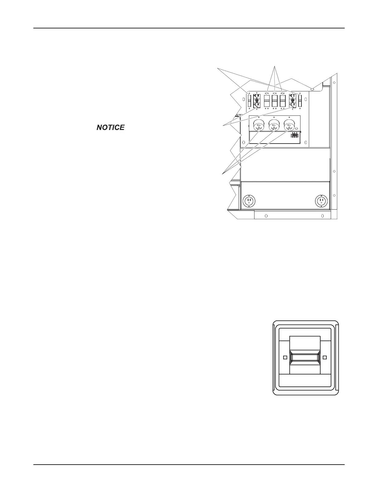
CUSTOMER CONVENIENCE RECEPTACLES
The unit is equipped with five receptacles. The 240/
120VAC twist-lock receptacles are rated at 50A each.
The 120VAC duplex receptacles are rated at 20A
each, with ground fault circuit interrupt (GFCI) protec-
tion. The receptacles are not routed through the main
circuit breaker. Each receptacle has its own circuit
breaker, located directly above or next to the recep-
tacle. Each breaker is sized to the maximum rating of
the corresponding receptacle.
Power to the receptacles is
available any time the generator
is running, even if the main circuit
breaker is OFF (O). Verify
equipment connected to the
receptacles is turned off before
turning the breakers on. Verify the
voltage selector switch is in the
proper position and that the
output voltage is correct for the
equipment connected to the
receptacles. Improper voltage
may cause equipment damage or
malfunction.
Figure 3-8. Receptacle and Breaker Locations
Note: When the voltage selector switch is in position for 480/277V 3Ø, voltage at the two GFCI receptacles is 139
volts and the voltage at the three twist-lock receptacles is 240/139 volts. Generac Mobile Products LLC does not
recommend using the receptacles in the 480V position. When the voltage selector switch is in position for 208/120V
3Ø, voltage at the three twist-lock receptacles and the two GFCI receptacles is 208/120 volts.
MAIN CIRCUIT BREAKER
The main circuit breaker is located on the main control panel (see Figure 2-4). When
the breaker is OFF (O), power is interrupted to the connection lugs, the optional cam
lock receptacles, and the generator. Once the connections have been made to the
connection lugs or the optional cam lock receptacles, and the unit has been started
and allowed to reach normal operating temperature, the breaker may be switched ON
(I).
The main circuit breaker will be tripped, disconnecting power to the connection lugs
and the optional cam lock receptacles if any of the following items occur while the unit
is running:
1. Overload of the generator circuits to the connection lugs or the optional cam
lock receptacles.
Figure 3-9. Main Circuit
Breaker
2. The door covering the connection lugs or the optional cam lock receptacles is opened.
3. If the emergency stop switch is activated.
120V GFCI
Receptacles
50A Circuit
Breakers
20A Circuit
Breakers
120/240V
Twist-Lock
Receptacles
00453
On/I
On/I
Off/O
Off/O
00452
 Loading...