9
NOTE:
All systems are equipped with the Inphase Monitor function,
and advisory indicators on the HMI system status will indicate
operation of the various solid state timers that control auto-
matic operation. By observing these indicators, the operator
can check the automatic operating sequences and times. For a
detailed description of the automatic operating sequences, see
the "Sequence of Operation" section.
5. When the test is complete, select Return to Normal and the
ATS will return to AUTOMATIC MODE. Retransfer back to the
NORMAL (UTILITY) power source should occur. The genera-
tor should shut down according to the timer settings.
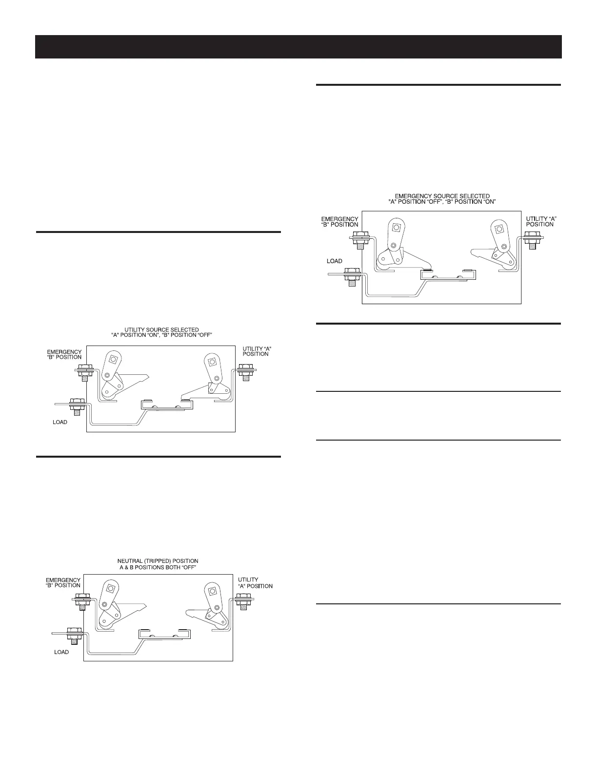
3.5 MAIN CONTACTS AT NORMAL (UTILITY)
The illustration shows the LOAD terminals connected to the
NORMAL (UTILITY) terminals. window “A” will display the word
“ON”; Window “B” the word “OFF” (Figure 7).
Figure 7 — Main Contact at Normal (Utility)
3.6 MAIN CONTACTS AT NEUTRAL
LOAD terminals are disconnected from both power supply ter-
minals. The word “OFF” will be displayed in both Windows “A”
and “B” (Figure 8). This occurs when the solenoid coil is kept
energized.
Figure 8 — Main Contacts at Neutral
3.7 MAIN CONTACTS AT STANDBY
(EMERGENCY)
LOAD terminals are connected to the standby (EMERGENCY)
power supply. Window “B” will display the word “ON”; Window
“A” the word “OFF” (Figure 9).
Figure 9 — Main Contacts at Standby (Emergency)
3.8 SEQUENCE OF OPERATION
When acceptable UTILITY source voltage is available, observe the
following sequences.
3.8.1 SEQUENCE 1 - VOLTAGE DROPOUT
• UTILITY source voltage drops below the Utility fail-low voltage
or is above Utility Fail-high voltage set point.
3.8.2 SEQUENCE 2 - LINE INTERRUPT DELAY
• UTILITY source voltage is above or below Utility fail range set-
ting.
• Line Interrupt Delay is initiated by the voltage out of range
condition.
• If UTILITY source voltage remains out of range longer than the
Delay setting, circuit board action closes the automatic start
circuit (Wires 178 and 183). When that circuit closes, the
engine cranks and starts as controlled by a circuit board in the
generator’s control panel.
• Once the standby generator starts and produces voltage, go to
Sequence 3.
3.8.3 SEQUENCE 3 - ENGINE MINIMUM RUN AND
WARMUP TIMERS
• The minimum run timer establishes the minimum length of time
for the generator to run before it can be shut down. The timer
prevents shutdown of a cold engine. The timer is adjustable
from 5 to 30 minutes; factory setting is 5 minutes.
• An engine warmup timer is also turned ON. This timer permits
the engine to stabilize and warm up before loads are transferred
to STANDBY. This timer is adjustable from 5 seconds to 3 min-
utes. Factory setting is 5 seconds.
Operation
 Loading...