Safety Rules .............................................................................1
General Information ..................................................................2
1.1 Introduction ...............................................................................2
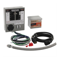
1.2 Equipment Description ...............................................................2
1.3 Transfer Mechanism ...................................................................3
1.4 Ratings — Data Label ................................................................3
1.5 Panel Board Enclosure ...............................................................3
1.6 TAS Controller System ...............................................................3
1.7 Safe Use of Transfer Switch .......................................................3
Installation ................................................................................3
2.1 Introduction to Installation ..........................................................3
2.2 Unpacking ..................................................................................3
2.3 Mounting ...................................................................................4
2.4 Connecting Power Source and Load Lines..................................4
2.5 Connecting Start Circuit Wires ...................................................5
2.6 Auxiliary Contacts ......................................................................5
Operation ..................................................................................6
3.1 Functional Tests & Adjustments ..................................................6
3.2 Manual Operation - ATS Contactor .............................................6
3.3 Voltage Checks ..........................................................................7
3.4 Electrical Operation ....................................................................8
3.5 Main Contacts at Normal (Utility)................................................9
3.6 Main Contacts at Neutral ............................................................9
3.7 Main Contacts at Standby (Emergency) ......................................9
3.8 Sequence of Operation ...............................................................9
3.9 Sequence of Operation Settings ................................................10
3.10 The Human Machine Interface (HMI) ........................................10
Maintenance ...........................................................................16
4.1 Operate Transfer Switch ...........................................................16
4.2 Clean and Inspect Transfer Switch ............................................16
4.3 Lubrication ...............................................................................16
4.4 Main Current Carrying Contacts ...............................................17
4.5 Batteries ..................................................................................17
Warranty ...................................................................Back Cover
Read the following information carefully
before attempting to install, operate or ser-
vice this equipment. Also read the instruc-
tions and information on tags, decals, and
labels that may be affixed to the transfer
switch. Replace any decal or label that is no
longer legible.
DANGER! Connection of a generator to an
electrical system normally supplied by an
electric utility shall be by means of suitable
transfer equipment so as to isolate the elec-
tric system from utility distribution system
when the generator is operating (Article 702
Optional Standby Systems, as applicable).
Failure to isolate electric system by these
means may result in damage to generator
and may result in injury or death to utility
workers due to backfeed of electrical energy.
The manufacturer cannot anticipate every possible circumstance
that might involve a hazard. The warnings in this manual, and on
tags and decals affixed to the unit are, therefore, not all-inclusive. If
using a procedure, work method or operating technique the manu-
facturer does not specifically recommend, ensure that it is safe for
others. Also make sure the procedure, work method or operating
technique chosen does not render the transfer switch unsafe.
Throughout this publication, and on tags and decals affixed to the
generator, DANGER, WARNING, CAUTION and NOTE blocks are
used to alert personnel to special instructions about a particular
operation that may be hazardous if performed incorrectly or care-
lessly. Observe them carefully. Their definitions are as follows:
After this heading, read instructions that, if not
strictly complied with, will result in serious
personal injury, including death.
Table of Contents
WARNING!
California Proposition 65
Engine exhaust and some of its constituents are known to the state of California to cause cancer,
birth defects, and other reproductive harm.
WARNING!
California Proposition 65
This product contains or emits chemicals known to the state of California to cause cancer,
birth defects, and other reproductive harm.
 Loading...