5
2.5 CONNECTING START CIRCUIT WIRES
2.5.1 ON-SITE GENERATOR CONNECTIONS
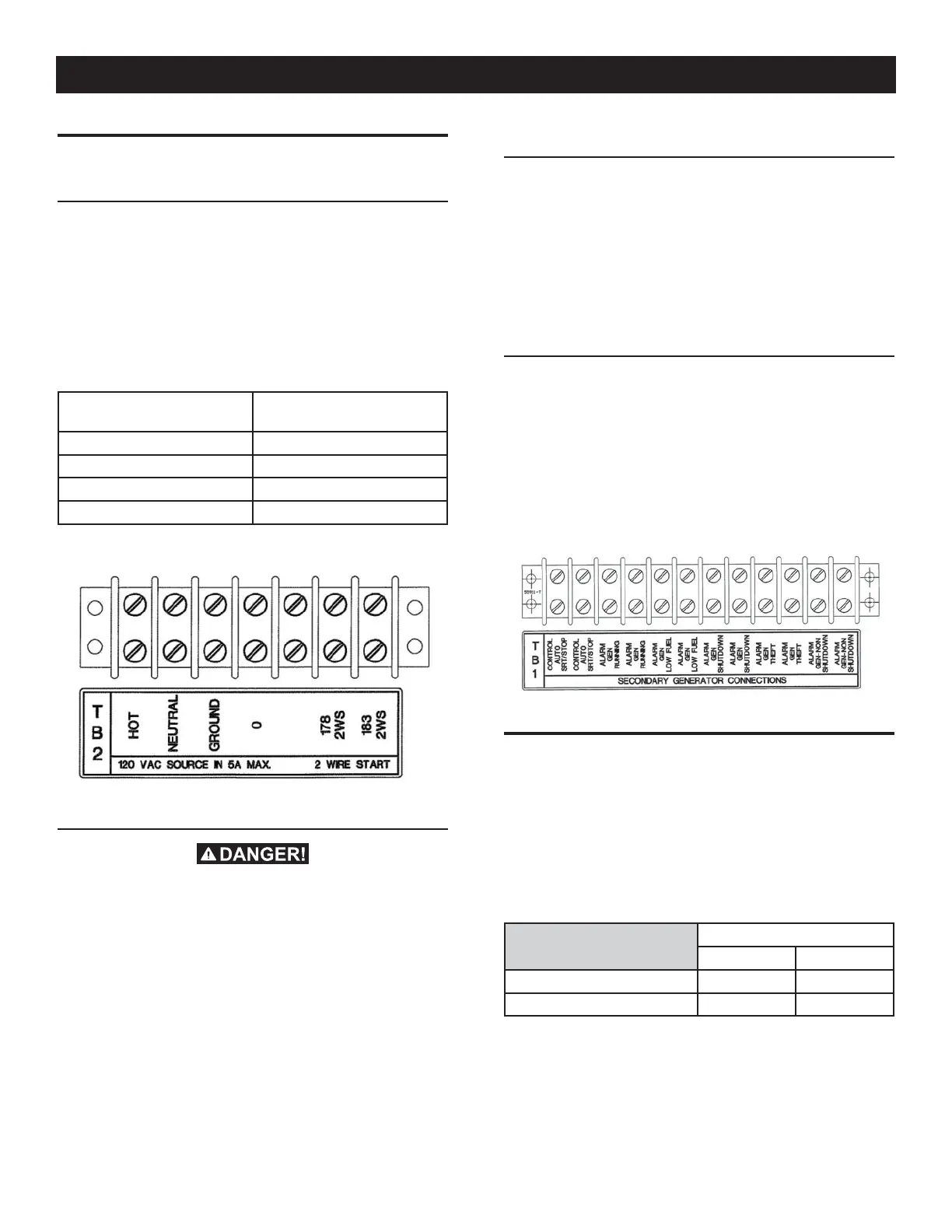
Connect suitable, approved wiring to transfer switch terminals
178 and 183 (see the following chart). Route these wires through
suitable, approved individual conduit and connect to identically
numbered terminals in the AC connection (lower) panel of the
generator set (see Figure 4).
Closure of Wire 178 and 183 circuit by switch circuit action must
result in generator engine cranking and startup.
Recommended wire gauge sizes for this wiring depends on the
length of the wire as recommended in the following chart:
MAXIMUM WIRE LENGTH
RECOMMENDED WIRE
SIZE
460 feet (140m) No. 18 AWG.
461 to 730 feet (223m) No. 16 AWG.
731 to 1,160 feet (354m) No. 14 AWG.
1,161 to 1,850 feet (565m) No. 12 AWG.
Figure 4 — On-site Generator Connections
2.5.2 BATTERY CHARGER CONNECTION (REQUIRED)
Disconnect all power from this unit before
making connections.
Connection steps (refer to Wiring Diagram 0J7612 on Generac
Website):
1. Ensure that utility power is OFF at this point.
2. Connect # 14 AWG (or larger) insulated wire (fused at the
source) with a 15A circuit maximum to terminals TB2-1,2,3
in the TAS and run this to the nearest 120 VAC single phase
critical load that will be supplied by the generator if utility
power is lost.
2.5.3 SECONDARY GENERATOR CONNECTIONS
The 2-wire start connections for the secondary generator are to be
made at the terminal blocks labeled "TB1 - Secondary Generator
Connections", the two terminals labeled "Control Auto Start/Stop".
This is typically done through a multi-wire cable to the secondary
generator.
Closure of the relay contacts across these terminals will occur
when the secondary generator is to run.
2.5.4 SECONDARY GENERATOR ANNUNCIATOR
CONNECTIONS
A terminal strip is provided to make the annunciator connections
from the Cam-lok box. A multi-conductor cable is provided with
the cam-lok enclosure (provided separately).
Route the multi-conductor cable into the TAS enclosure, be sure to
keep cable away from power leads. Secure in place using ty-wraps
or other appropriate fasteners. Connect the wires to the terminal
strip matching the functions declared on the terminal strip decal.
Figure 5 — Secondary Generator Connections
2.6 AUXILIARY CONTACTS
There is access to Auxiliary Contacts on the transfer switch to
operate customer accessories, remote advisory lights, or remote
annunciator devices. A suitable power source must be connected
to the COMMON (C) terminal. The contacts shown as FACTORY in
Figure 5 are connected at the factory for operating transfer switch
advisory lights. The contacts shown as auxiliary are available for
customer use.
Contact operation is shown in the following chart:
Switch Position
Utility Standby
Common to Normally Open Closed Open
Common to Normally Closed Open Closed
NOTE:
Auxiliary Contacts are rated 10 amps at 125 or 250 volts AC.
DO NOT EXCEED THE RATED VOLTAGE AND CURRENT OF THE
CONTACTS.
Installation
 Loading...