3
This UL listed transfer switch is used for emergency standby sys-
tems only (NEC 700 and 701). Additional ratings are on the decals
attached to the inside of the enclosure door.
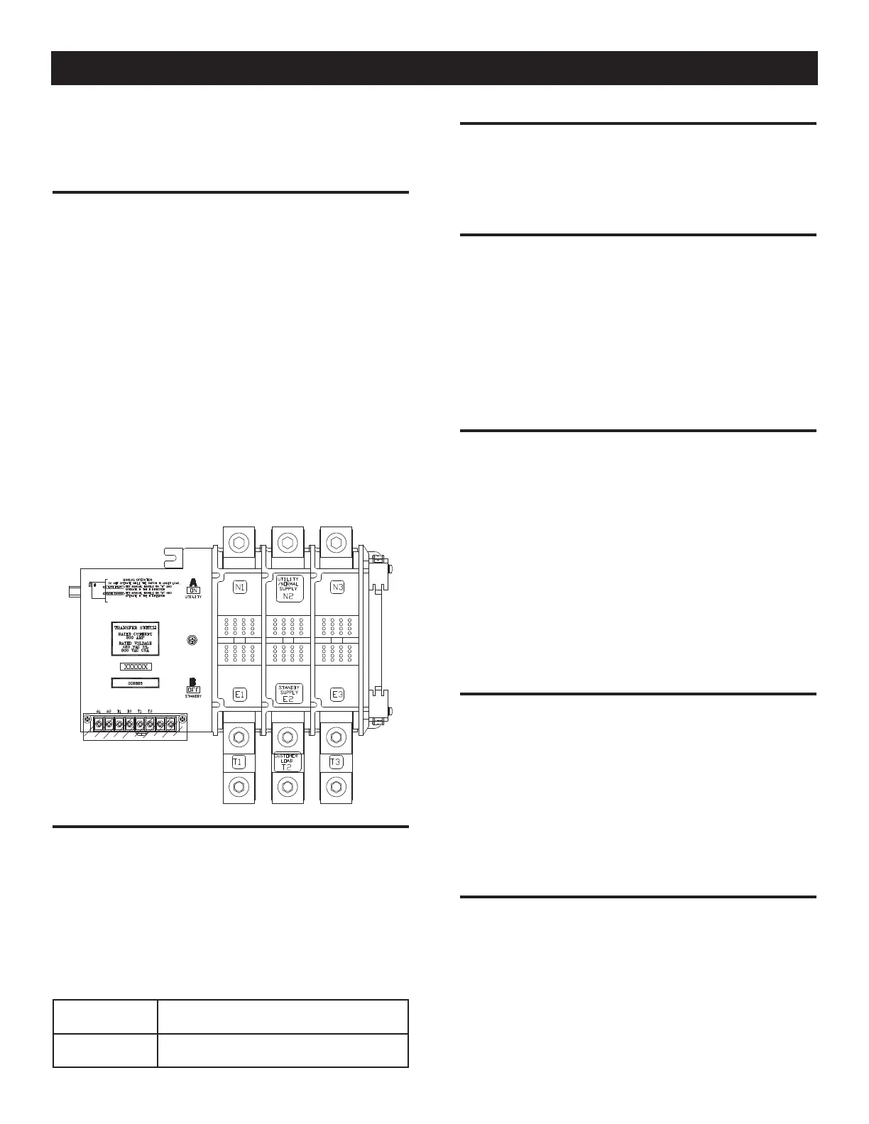
1.3 TRANSFER MECHANISM
• The transfer mechanism houses the main, current carrying con-
tacts, along with other mechanical and electrical components
required for operating the switch (Figure 2). Main contacts are
actuated by a single solenoid, are electrically operated and
mechanically held. Power for that coil’s operation is taken from
the side to which the LOAD is being transferred. Therefore,
transfer to any power source cannot occur unless that power
source is available to the switch.
• LOAD (or “T”) contacts are bolted to an insulated plastic pole
piece and are stationary. The NORMAL (UTILITY) and STANDBY
(EMERGENCY) contacts are moveable. The contacts are actu-
ated by means of a closing coil and mechanical linkage. The
pole assemblies which retain the stationary moveable main
contacts are assembled together and retained by through-bolts.
Either 2, 3 or 4-pole assemblies may be used to form a 2 or
3-pole mechanism.
Figure 2 — The Transfer Mechanism
1.4 RATINGS — DATA LABEL
This TAS is rated 200 amp at 120/240 VAC single phase or,
120/208 or 120/240 VAC three phase. A DATA LABEL is per-
manently affixed to the transfer switch subplate. Use this TAS
only within the specific limits shown on the DATA LABEL and the
application decal located on the inside, upper center of the cabinet.
When requesting information or ordering parts for this equipment,
make sure to include all information from the DATA LABEL. Record
the Model and Serial numbers in the space provided.
MODEL #
SERIAL #
1.5 PANEL BOARD ENCLOSURE
The standard TAS switch enclosure is a UL type 3R. UL type 3R
enclosures are intended for outdoor installation but can be mount-
ed indoors as well. This enclosure provides protection against rain
and sleet, and is undamaged by the formation of ice.
1.6 TAS CONTROLLER SYSTEM
The TAS control system is made up of a control pcb and Human
Machine Interface (HMI).
The HMI is mounted on the door and is the operator access to
the transfer switch settings and status. See section 3.10 for more
details.
The TAS controller is mounted on the left side of the TAS. This
controller monitors the utility voltage and controls the operation
of the transfer switch contactor. All settings and adjustments are
made through the door mounted HMI.
1.7 SAFE USE OF TANSFER SWITCH
Before installing, operating or servicing this equipment, read the
SAFETY RULES (inside front cover) carefully. Comply strictly with
all SAFETY RULES to prevent accidents and/or damage to the
equipment. The manufacturer recommends making a copy of the
SAFETY RULES and post them near the transfer switch. Also, be
sure to read all instructions and information found on tags, labels
and decals affixed to the equipment.
Three publications that outline the safe use of transfer switches
are the following:
• NFPA 70; National Electrical Code
• UL 1008, STANDARD FOR SAFETY-AUTOMATIC TRANSFER
SWITCHES
• UL 67, STANDARD FOR SAFETY-PANEL BOARDS
2.1 INTRODUCTION TO INSTALLATION
This equipment has been wired and tested at the factory. Installing
the switch includes the following procedures:
• Unpacking the TAS.
• Mounting the enclosure.
• Connecting power source and load leads.
• Connecting the generator start circuit.
• Connecting any auxiliary contact (if needed)
• Installing/connecting any options and accessories.
• Testing functions.
2.2 UNPACKING
Carefully unpack the transfer switch. Inspect closely for any dam-
age that might have occurred during shipment. The purchaser
must file with the carrier any claims for loss or damage incurred
while in transit.
Check that all packing material is completely removed from the
switch prior to installation.
Installation
 Loading...