Installation
Integrated Load Center Owner’s Manual 7
Section 3: Installation
Introduction to Installation
This equipment has been wired and tested at the factory.
Installing the switch includes the following procedures:
•Unpacking the TTS (ILC).
•Mounting the enclosure.
•Connecting power source and load leads.
•Connecting the generator start circuit.
•Connecting any auxiliary contact (if needed).
•Installing/connecting any options and accessories.
•Testing functions.
Mounting the Enclosure
•Mounting dimensions for the transfer switch enclosure
are in this manual. Enclosures are typically wall-
mounted. See Drawings and Diagrams.
IMPORTANT NOTE: To eliminate the possibility of
debris contamination, never drill inside the
enclosure.
1. Drill the appropriate size holes for mounting
hardware at marked hole locations.
2. Mount transfer switch to mounting surface with
appropriate fasteners.
3. Protect the switch against impact at all times, and
against construction grit and metal chips. Never
install a transfer switch that has been damaged.
NOTE: Install the transfer switch as close as possible to
the electrical loads that are to be connected to it.
NOTE: Transfer switch must be mounted vertically.
To prevent switch distortion, level all mounting points. If
necessary, use washers behind mounting holes to level
the unit.
Connecting Power Source and
Load Lines
IMPORTANT NOTE: All installations must comply
with national, state, and local codes. It is the
responsibility of the installer to perform an
installation that will pass the final electrical
inspection.
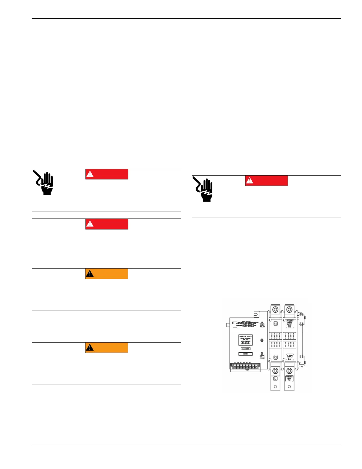
2-Pole Mechanism
The 2-Pole mechanism (Figure 3-1) utilizes a single
solenoid design. Utility connections are N1 & N2. Load
terminals are T1 & T2. Standby terminals are E1 & E2.
Figure 3-1. Typical 2-Pole Transfer Mechanism
(000123)
DANGER
Electrocution. Turn utility supply OFF before
working on utility connections of the transfer
switch. Failure to do so will result in death or
serious injury.
(000119)
Equipment malfunction. Installing a dirty or damaged
transfer switch will cause equipment malfunction and
will result in death or serious injury.
DANGER
(000182a)
WARNING
Equipment damage. Only qualified service personnel may
install, operate, and maintain this equipment. Failure to follow
proper installation requirements could result in death, serious
injury, and equipment or property damage.
WARNING
Personal injury. Excessive weight. Use only
appropriate lifting eyes and lifting equipment to
lift unit. Improper lifting techniques could result in
equipment damage, death or serious injury.
(000224)
Electrocution. Turn utility and emergency
power supplies to OFF before connecting
power source and load lines. Failure to do so
will result in death or serious injury.
(000116)
DANGER
 Loading...


