Operation
Integrated Load Center Owner’s Manual 13
Generator Voltage Checks
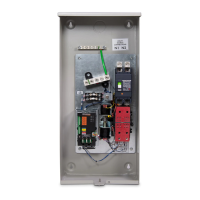
1. Inside the transfer switch enclosure, set the main-
tenance disconnect switch to MANUAL.
2. If the generator is so equipped, set the AUTO/OFF/
MANUAL switch to OFF.
3. On the ATS mechanism, check that the word “ON”
is visible in Window “A”, the word “OFF” in Window
“B”. See MANUAL OPERATION for location of “A”
and “B” windows.
4. Locate the 4-pin connector on the battery charger.
Plug the 4-pin harness connector into the battery
charger. Reset battery charger by momentarily
pressing up on toggle switch.
IMPORTANT NOTE: DO NOT PROCEED UNTIL
STEPS 1, 2, 3, AND 4 HAVE BEEN COMPLETED.
NOTE: If both utility and generator sources are
unavailable for more than 24 hours, disconnect the
battery by unplugging the 4-pin connector on the battery
charger.
5. Turn on the normal (utility) power supply to the
transfer switch, with whatever means provided
(such as the main line circuit breaker [MLCB]).
6. Reset battery charger by momentarily pressing up
on battery charger toggle switch.
IMPORTANT NOTE: The transfer switch is now
electrically hot. Proceed with caution.
7. With an accurate AC voltmeter, check the phase-
to-phase (line-to-line) and phase-to-neutral (line-to-
neutral) voltages present at transfer mechanism
terminals N1 and N2 (if so equipped), and neutral.
SUPPLIED VOLTAGES MUST BE FULLY
COMPATIBLE WITH TRANSFER SWITCH RATED
VOLTAGE.
8. Referring to the standby generator owner’s
manual, verify the generator engine has been
properly serviced and prepared for use. Then start
the generator engine manually. Let the engine
stabilize and warm up for a few minutes.
9. Turn on the standby (generator) power supply to
the transfer switch by whatever means provided
(such as the MLCB).
10. With the generator running, check that the
generator source available LED on the enclosure
door is on.
11. With an accurate AC voltmeter, check phase-to
phase (line-to-line) and phase-to neutral (line-to
neutral) voltages present at transfer mechanism
terminals E1 and E2 (if equipped). Verify AC
frequency at those terminals. The engine governor
may require adjustment if frequency is incorrect.
Generator AC output voltage and frequency must
be compatible with transfer switch rated voltage
and frequency.
12. If supplied voltage or frequency is incorrect, refer to
appropriate standby generator diagnostic manual.
Adjust engine governed speed if AC frequency is
incorrect. Adjust generator’s voltage regulation to
correct the problem if voltage is incorrect.
13. When supplied voltage and frequency is correct,
shut down the engine manually.
14. Connect the transfer switch load to the transfer
switch when “Voltage Checks” section has been
completed. Connect the load to the transfer switch
by whatever means provided (such as branch
circuit, circuit breaker[s]), then proceed with Main
Contacts at Normal (Utility).
(000129)
DANGER
Electrocution. High voltage is present at
transfer switch and terminals. Contact with live
terminals will result in death or serious injury.
(000227)
Electric Shock. Supply voltages of power lines
must be compatible with transfer switch.
Incompatible supply voltages could result in
equipment damage, death or serious injury.
WARNING

 Loading...


