Operation
Integrated Load Center Owner’s Manual 21
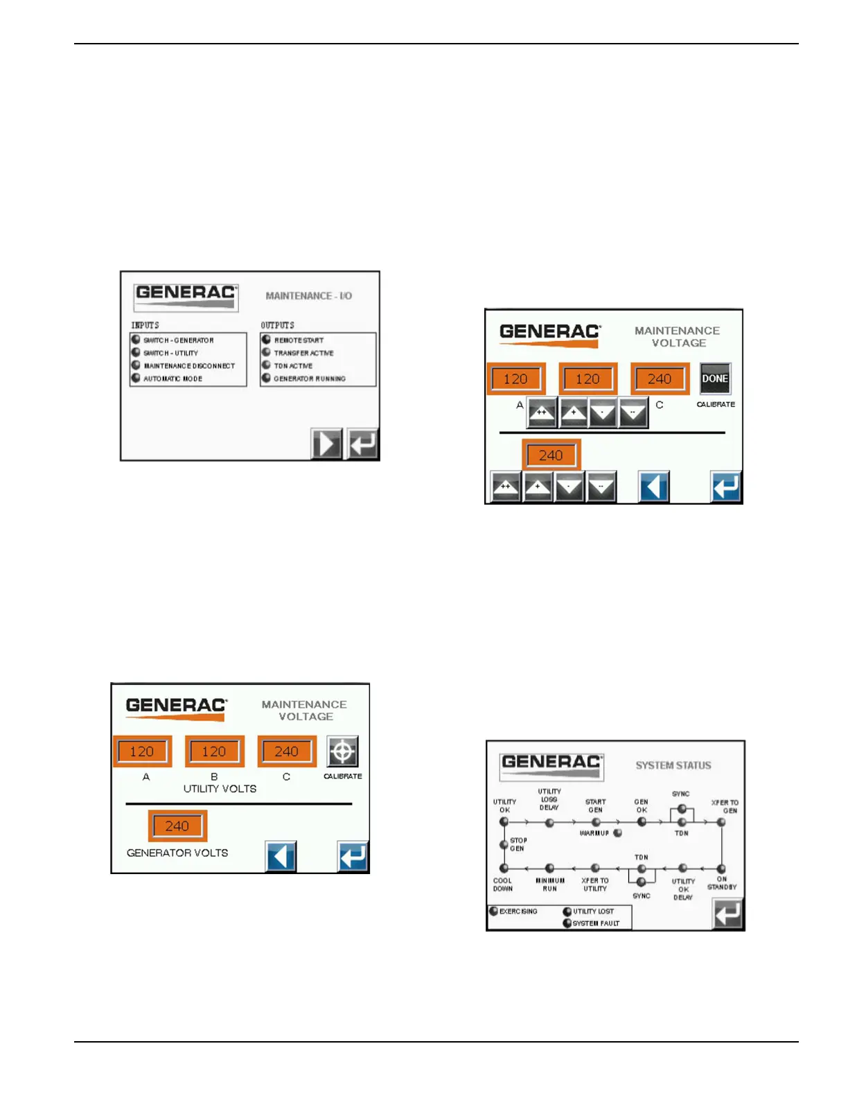
Input/Output Signal Maintenance
See Figure 4-15. To access the second screen, press
the right arrow button. To return to the system
configuration menu screen press the return arrow.
The indicator to the left of the individual input or output
text will indicate the status of the input. A green color
indicates the input or output is active and the condition it
is indicating is true. A black color will indicate the input or
output is not active and the condition it is indicating is not
true. For the maintenance disconnect indicator; red
means MANUAL and green means AUTO.
Figure 4-15. Input/Output Signal Maintenance
Voltage Measurement Display
This is the utility and generator voltage inputs screen. To
access the Maintenance I/O screen, press the left arrow
button (Figure 4-16). To return to the system
configuration menu screen press the return arrow.
To calibrate the individual inputs, press the CALIBRATE
button. This will display the voltage measurement
adjustment buttons. For single phase systems, C is the
sum of A and B voltages.
Figure 4-16. Voltage Measurement Maintenance
Voltage Measurement Maintenance
This screen is used to calibrate the utility and generator
voltage inputs (Figure 4-17). To access the first screen,
press the left arrow button. To return to the system
configuration menu screen press the return arrow.
To calibrate the individual inputs, press the screen button
displaying the value to the changed. The "++", “+” and "--
", “-“ screen buttons can be used to change the displayed
value to match the measured value. The "++" and "--"
buttons will change the setting at a faster rate than the
"+" and "-" buttons.
When all values have been updated, press the DONE
button to update the settings.
Figure 4-17. Voltage Measurement Maintenance
System Status
The system status screen is used to convey what step of
the sequence the transfer switch controller is currently in.
This screen can be used for operation and
troubleshooting. See Figure 4-18.
The indicators will change colors to indicate whether the
function they represent is active or inactive; green or red
for active, black for inactive.
To return to the system configuration menu screen press
the return arrow.
Figure 4-18. System Status
 Loading...


