Operation
18 Integrated Load Center Owner’s Manual
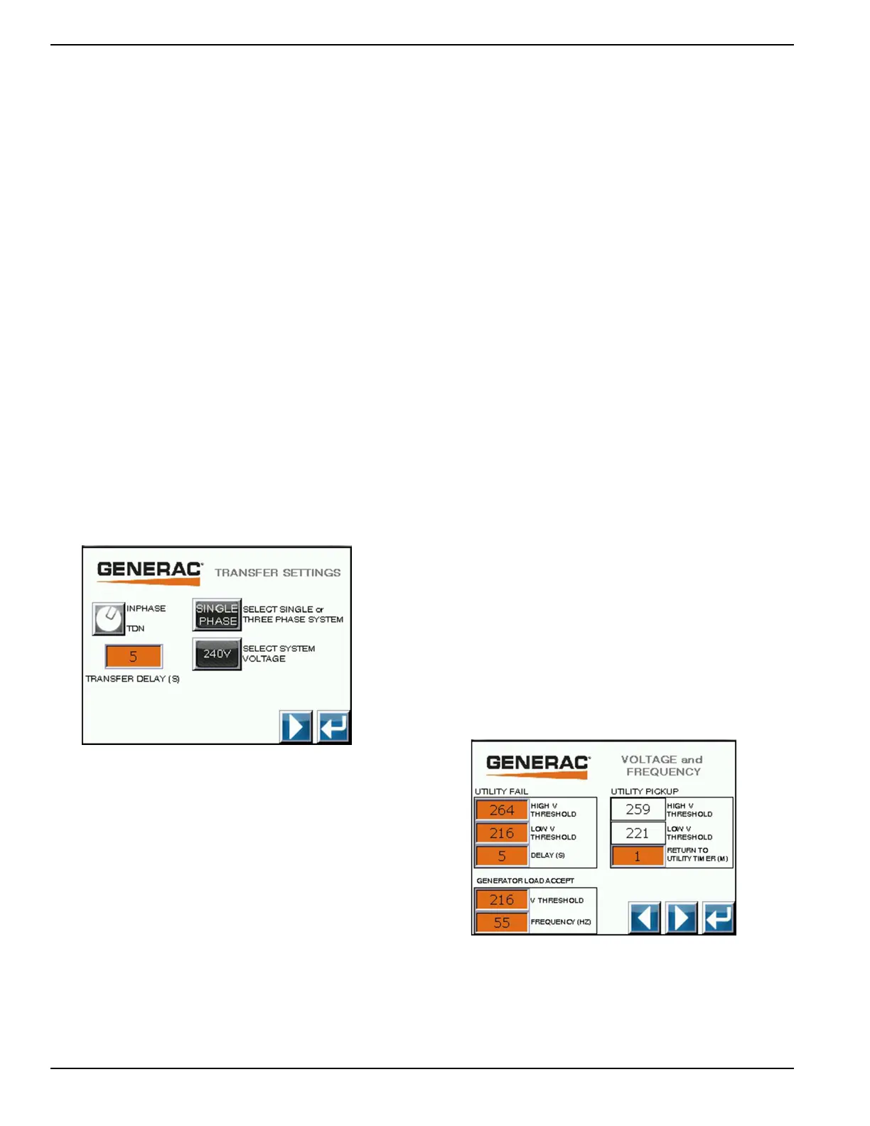
Transfer Switch Settings #1
The transfer switch settings are divided into three
screens. The second screen can be accessed by
pressing the right arrow button. To return to the system
configuration menu screen press the return arrow
(Figure 4-7).
Inphase or TDN - The inphase or TDN selection is made
by pressing the button next to it. The selection toggles
with each press of the button. The transfer switch waits
for utility and standby voltage phasors to match prior to
transfer to utility.
Transfer Delay Neutral (TDN) - To set the transfer delay,
press the button where the current transfer delay is
displayed. Enter the time delay neutral time in seconds
using the pop-up box. The acceptable range is shown on
the screen. Press ENTER to update.
System Voltage Selection - Perform this selection
before the system voltage phase selection. Press the
button labeled SELECT SYSTEM VOLTAGE to set the
system voltage. The display will toggle between 208V
and 240V. Note: 208V is only available in a 3-phase
system voltage.
System Voltage Phase Selection - Press the button
labeled SELECT SINGLE or 3-PHASE SYSTEM to set
the number of phases of the system. The display will
toggle between single and 3-phase with a 240V system.
Figure 4-7. Transfer Switch Settings #1
Transfer Switch Settings #2
This is the second screen of the transfer switch settings
screens. The first or third screen can be accessed by
pressing the left or right arrow buttons. To return to the
system configuration menu screen press the return arrow
(Figure 4-8).
Utility Fail-High Voltage Threshold - Press the screen
button that is displaying the current value to set the utility
fail-high voltage threshold value. Enter the voltage that
will signal a utility fail condition using the pop-up box. The
acceptable range is shown on the screen. Press ENTER
to change setting.
Utility Fail-Low Voltage Threshold - Press the screen
button that is displaying the current value to set this
value. Enter the voltage that will signal a utility fail
condition using the pop-up box. The acceptable range is
shown on the screen. Press ENTER to change setting.
Utility Fail Delay - This is the amount of time that the
utility voltage must remain out of range before a utility fail
sequence will be initiated. Press the screen button that is
displaying the current value to set this value. Enter the
delay time in seconds using the pop-up box. The
acceptable range is shown on the screen. Press ENTER
to change setting.
Utility Pickup-High Voltage Threshold - This box
displays the voltage that the utility must be at or under to
be considered good. It is equal to the utility fail high
voltage threshold minus 5 volts.
Utility Pickup-Low Voltage Threshold - This box
displays the voltage that the utility must be at or over to
be considered good. It is equal to the utility fail low
voltage threshold plus 5 volts.
Utility Pickup Delay - This is the amount of time that the
utility voltage must remain within range before a utility
pickup sequence will be initiated. Press the screen button
that is displaying the current value to set this value. Enter
the delay time in minutes using the pop-up box The
acceptable range is shown on the screen. Press ENTER
to change setting.
Generator Load Accept-Voltage Threshold - Press the
screen button that is displaying the current value to set
this value. Enter the voltage that will signal a utility pickup
condition using the pop-up box. The acceptable range is
shown on the screen. Press ENTER to change setting.
Generator Load Accept-Frequency - Press the screen
button that is displaying the current value to set this
value. Enter the frequency that will signal a utility pickup
condition using the pop-up box. The acceptable range is
shown on the screen. Press ENTER to change setting.
Figure 4-8. Transfer Switch Settings #2
 Loading...


