General Information
Integrated Load Center Owner’s Manual 5
Ratings—Data Label
This ILC is rated 200A at 120/240 or 120/208 VAC single
phase. The Short Circuit Withstand and Close-On
Withstand rating is 35,000 Amps. A data label is
permanently affixed to the transfer switch subplate. Use
this ILC only within the specific limits shown on the data
label and the application decal located on the inside
lower left side of the cabinet.
When requesting information or ordering parts for this
equipment, make sure to include all information from the
data label. Record the model and serial numbers in the
space provided on the front cover for future reference.
Panel Board Enclosure
The standard TTS (ILC) switch is a NEMA type 1 indoor
enclosure. Outdoor enclosure is optional.
Safe Use of Transfer Switch
Before installing, operating, or servicing this equipment,
read the Safety Rules carefully. Strictly comply with all
safety rules to prevent accidents and/or damage to the
equipment. The manufacturer recommends that a copy
of the safety rules be posted near the transfer switch.
Read all instructions and information found on tags,
labels, and decals affixed to the equipment.
Publications that outline the safe use of transfer switches
are the following:
•NFPA 70; National Electrical Code
•UL 1008, STANDARD FOR SAFETY-AUTOMATIC
TRANSFER SWITCHES
•UL 67, STANDARD FOR SAFETY-PANEL BOARDS
The automatic transfer switch is used for transferring
electrical load from a utility (normal) power source to a
generator (standby) power source. Transfer of electrical
loads occurs automatically when the utility power source
has failed or is substantially reduced, and the generator
source voltage and frequency have reached an
acceptable level. The transfer switch prevents electrical
feedback between two different power sources (such as
the utility and generator sources) and codes require it in
all standby electric system installations.
The transfer switch consists of a transfer mechanism, a
control relay, fuses, terminal strip, and fuse holder for
connection of sensing wires.
The transfer switch is listed for use on optional standby
systems only (NEC 702).
Transfer Switch Mechanism
The switch is used with a single-phase system, when the
single-phase neutral line is to be connected to a neutral
lug and is not to be switched.
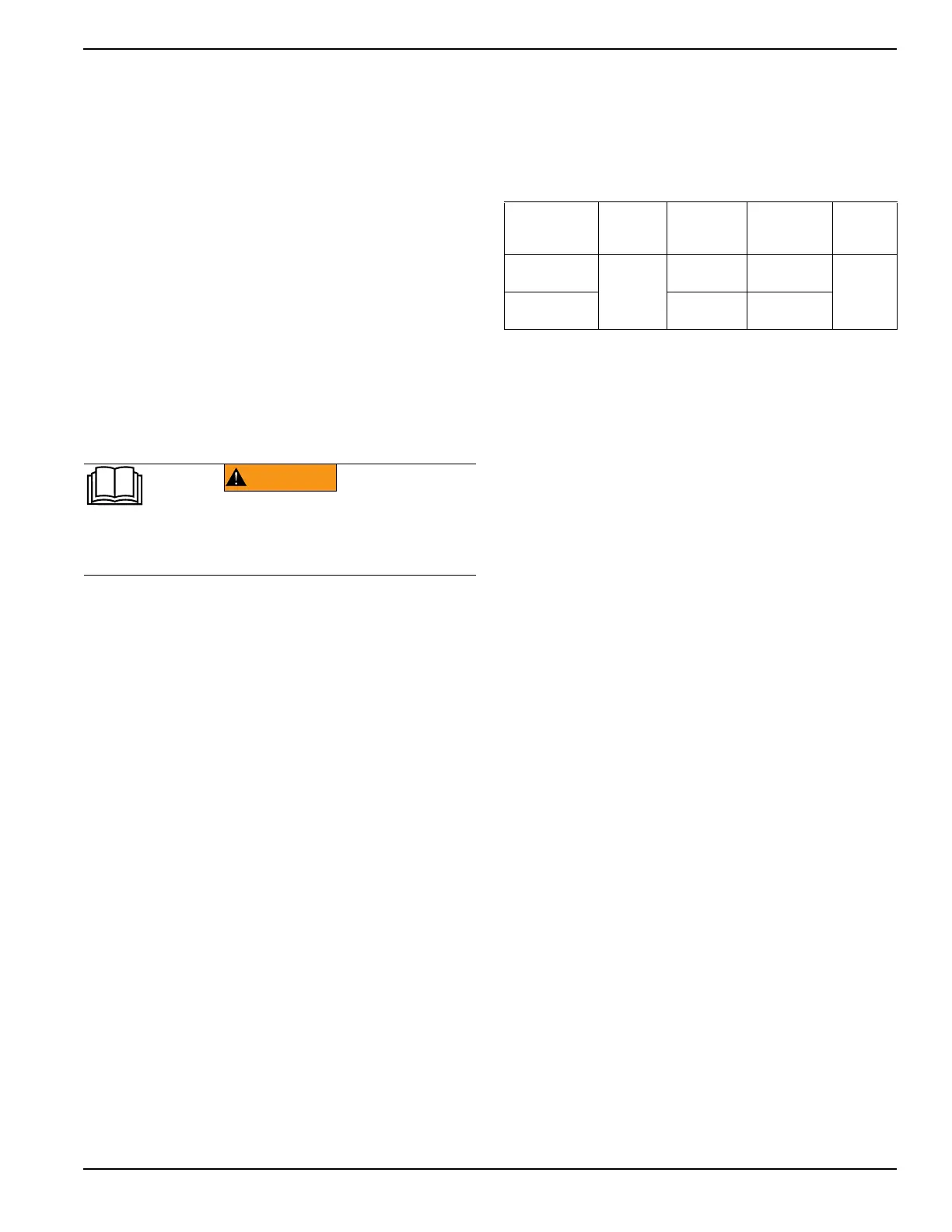
Solderless, screw-type terminal lugs are standard.
The conductor size range is as follows:
Transfer Switch Data Decal
A data decal is permanently affixed to the transfer switch
enclosure. Use this transfer switch only with the specific
limits shown on the data decal and on other decals and
labels that may be affixed to the switch. This will prevent
damage to equipment and property.
When requesting information or ordering parts for this
equipment, include all information from the data decal.
For future reference, record the model and serial
numbers in the space provided on the front cover of this
manual
Publications that outline the safe installation and
manufacturing of transfer switches are the following:
•NFPA 70; National Electrical Code
•UL 1008, STANDARD FOR SAFETY-AUTOMATIC
TRANSFER SWITCHES
•UL67 Panel boards
NOTE: It is essential to use the latest version of any
standard to ensure correct and current information.
(000100a)
WARNING
Consult Manual. Read and understand manual
completely before using product. Failure to
completely understand manual and product
could result in death or serious injury.
Power
Connections
Current
Rating
Lug Wire
Range
Lug
Tightening
Torque
Lug
Temp.
Rating
Breaker
200A
6 AWG -
300 MCM
250 in-lbs
(28.2 Nm)
167 °F
(75 °C)
Transfer
Switch
4 AWG -
400 MCM
375 in-lbs
(42.4 Nm)
 Loading...


