Electrical connection E 212 R1 / E 212 R / E 212
GB 8
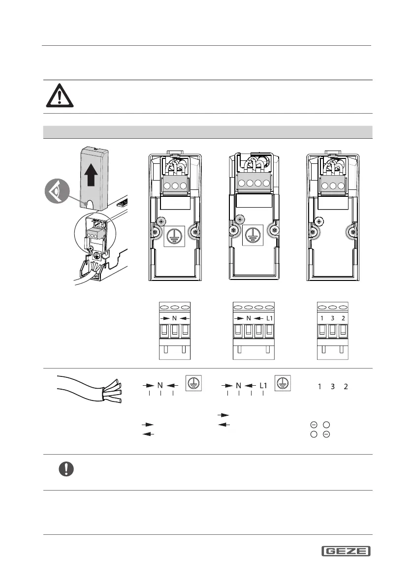
5 Electrical connection
DANGER!
Danger of electric shock!
When connecting the drive, make sure there is no mains
voltage at the supply terminals!
E 212 R1 /230 V E 212 R /230 V E 212 /24 V
Break to the cable duct ope-
ning. With cable diameter >
11 mm, the side cap must be
sawn out correspondingly
larger.
After connection, put the
side cap back in place and
screw tightly.
230V N 230V PE
230V N 230V 230V PE 24V 24V
Retract
Extend
Retract, pulse
Extend, pulse
L1 Permanent
phase 230 V
1 2
+
Retract
1
+
2 Extend
E 212 /24 V
Line control
by connecting wire "3"
to the last motor of the group.
1 Supply 24 V DC
2 Supply 24 V DC
3
Line control
For one operating
point, permanent
signal 230 V.
For several operating
points with integrated
self-locking module,
pulse signals 230 V.
Change the polarity
of the supply voltage,
RWA controls
 Loading...