System Appearance - 19 -
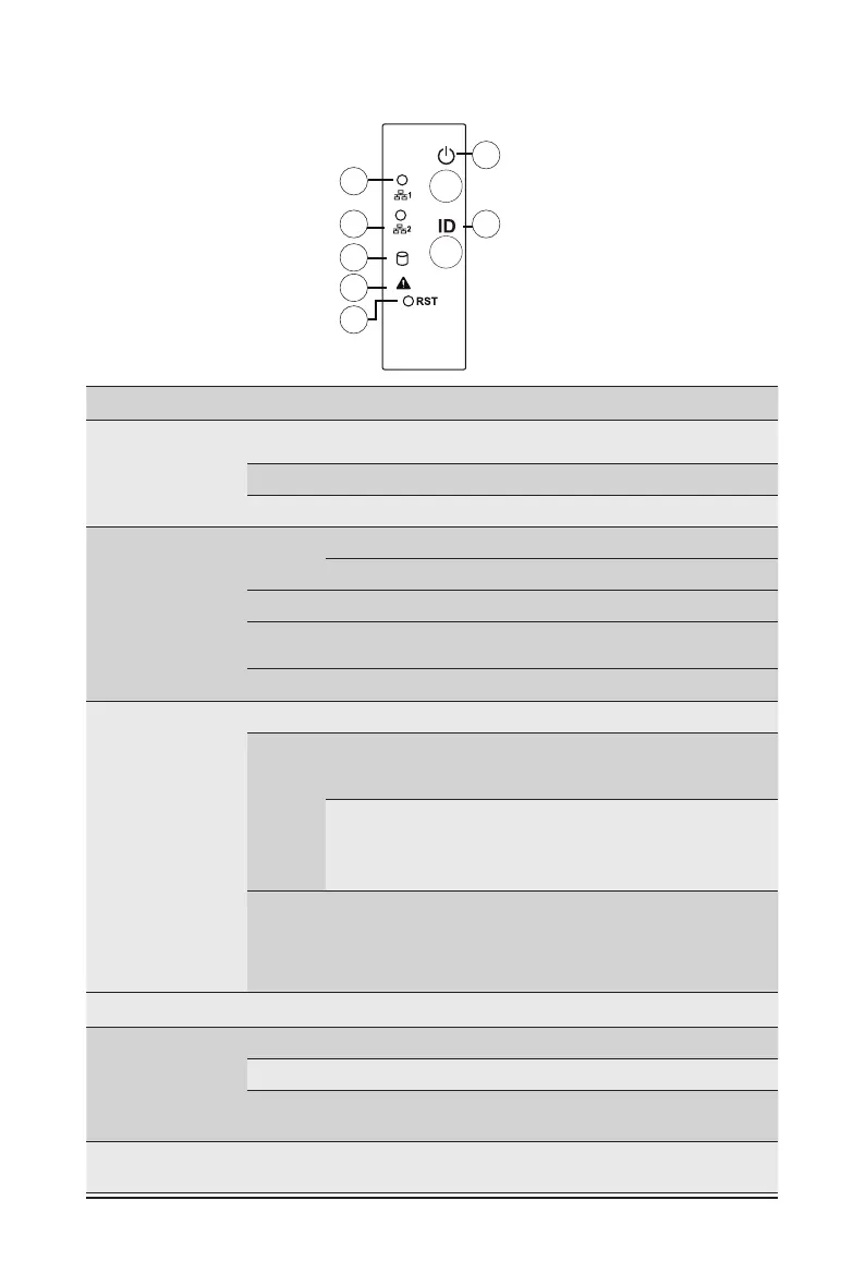
2-3 Front Panel Buttons and LEDs
No.
Name Color Status Description
1/2.
LAN1/2
Active/
Link LED
Green On
Indicates a link between the system and the network or
no access.
Green Blink
Indicates data trasmission or receiving is occuring.
N/A Off
Indicates no data transmission or receiving is occuring.
3.
HDD Status
LED
Green
On Indicates locating the HDD.
Blink Indicates accessing the HDD.
Amber On Indicates HDD error.
Green /
Amber
Blink Indicates HDD rebuilding.
N/A Off Indicates no HDD access or no HDD error.
4.
System
Status LED
Green On
Indicates system is operating normally.
Amber
On
Indicates a critical condition, may include:
- System fan failure
- System temperature
Blink
Indicates non-critical condition, may include:
- Redundant power module failure
- Temperature and voltage issue
- Chassis intrusion
N/A Off
Indicates system is not ready, may include:
- POST error
- NMI error
- Processor or terminator is missing
5.
Reset Button -- -- Press this button to reset the system.
6.
Power Button
with LED
Green On Indicates the system is powered on.
Green Blink System is in ACPI S1 slate (sleep mode).
N/A Off
Indicates system is not powered on or in ACPI S5 slate
(power off) or system is in ACPI S4 slate (hibernation mode).
7.
ID Button
with LED
-- -- Press this button to activate system identication.
1
2
3
4
5
6
7
 Loading...