- 77 - BIOS Setup
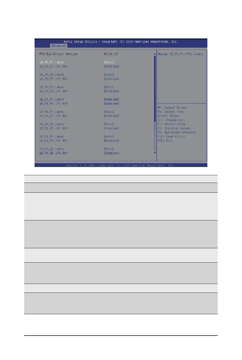
5-2-10 PCI Subsystem Settings
Parameter Description
PCI Bus Driver Version Displays the PCI Bus Driver version information.
U2_P0_P1 / U2_P0_P2 / U2_P0_P3 /
U2_P1_P0 / U2_P1_P1 / U2_P1_P2 /
U2_P1_P3 / U2_P0_G3 / U2_P1_G1
Lanes
(Note1)
Change the PCIe lanes.
Options available:
Disabled / Auto / x16 / x8 x8 / x8 x4 x4 / x4 x4 x8 / x4 x4 x4 x4
Default setting is Auto.
U2_P0_P1 / U2_P0_P2 / U2_P0_P3 /
U2_P1_P0 / U2_P1_P1 / U2_P1_P2 /
U2_P1_P3 / U2_P0_G3 / U2_P1_G1
I/O ROM
(Note1)
When enabled, this setting will initialize the device expansion
ROM for the related PCI-E slot.
Options available: Enabled/Disabled. Default setting is Enabled.
Onboard LAN 1 Controller
(Note2)
Enable/Disable the onboard LAN devices.
Options available: Enabled/Disabled. Default setting is Enabled.
Onboard LAN 1 I/O ROM
(Note2)
Enable/Disable the onboard LAN devices and initializes device
expansion ROM.
Options available: Enabled/Disabled. Default setting is Enabled.
PCI Devices Common Settings
Above 4G Decoding
Enable/Disable memory mapped I/O to 4GB or greater address
space (Above 4G Decoding).
Options available: Enabled/Disabled. Default setting is Enabled.
(Note1) This section is dependent on the available PCIe Slot.
(Note2) This section is dependent on the available LAN controller.
 Loading...