Supplied By www.heating spares.co Tel. 0161 620 6677
15
6.1 Appliance Pack
Please check the contents of packs as shown in diagram 6.1.
The packs are located in the top polystyrene packing.
Remove the carton sleeve and top pack then lift the boiler and
its polystyrene base support out of the lower pack.
6.2 Site Requirements
The boiler mounting wall should be suitable for the weight of
the appliance and be true and at.
NOTE: Due to the varied site conditions we do not supply
xings and advise that the installer should supply those which
are suitable.
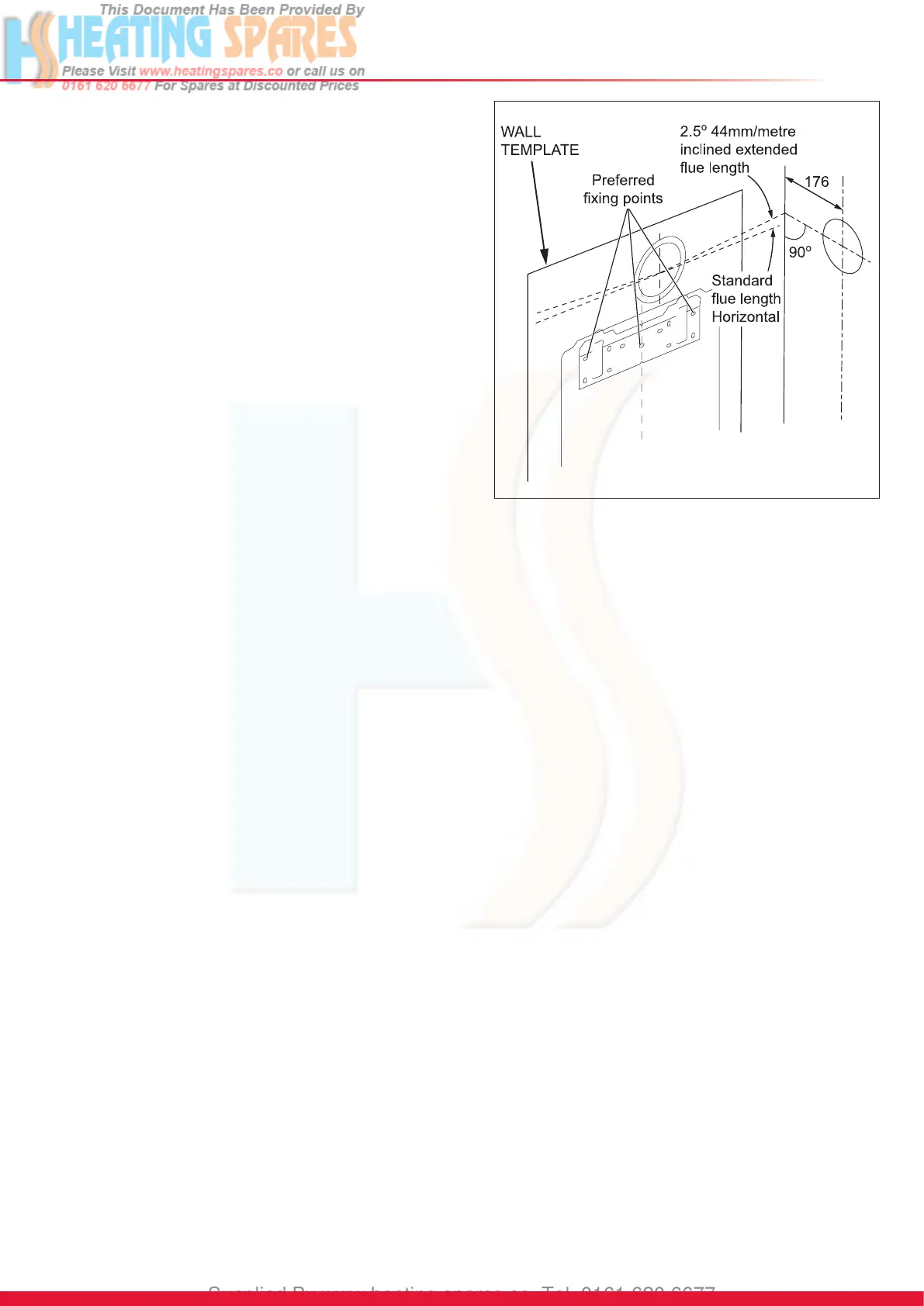
6.3 Wall Template
Take the wall template from the document pack located within
the top polystyrene packing and place in the desired position
on the wall, giving due consideration to the required boiler
clearances, see section 3, and the ue you are tting.
Mark the position of the ue centre, if tting a side ue, extend
the ue centre line into the corner then 158mm along the
adjacent wall.
For extended side ues, the ue hole centre should be
determined by extending the dashed inclined line on the
template to the side wall. This dashed line is drawn at 44mm/
metre (2.5°) rise from the boiler. Where this line reaches the
side wall, a horizontal line should be marked. The vertical
centre line of the ue should then be marked at 176mm from
the back wall.
To allow for the ue passing through the wall at this angle
a 125mm hole should be drilled irrespective of internal or
external installation.
Remove the wall template whilst drilling the ue hole.
6.4 Flue Hole Cutting
External access ue installation can use a 105mm diameter
core drill.
Internal access only ue installation will need a 125mm
diameter core drill.
NOTE: The ue is designed with an internal fall of 44mm/
metre (2.5°), therefore the hole can be drilled horizontally.
If ue extension pipes are to be used then a core drill size of
125mm is required. This will allow the extension pieces to
slope at 44mm/metre (2.5°) towards the boiler.
6 Installation Preparation
13853
Diagram 6.2
 Loading...