EasyManua.ls Logo

Glow-worm 24cx User Manual

Glow-worm 24cx
68 pages
To Next Page IconTo Next Page
To Previous Page IconTo Previous Page
Page #16 background image
Supplied By www.heating spares.co Tel. 0161 620 6677
16
8.1 Systems Connection
Remove the protective caps from the boiler connections.
NOTE: The appliance may contain a small amount of water,
place a water container beneath the boiler connections
Assemble and secure the pre formed copper tails to their
respective isolation valves making sure of their correct
orientation, see diagram 8.1.
Fit the isolation valves/copper tails with seals to the appliance
as shown in diagram 8.1
Make sure that all connections are secured in the sequence
shown on diagram 8.1.
There are ats on the body of the valves for locating a
spanner to aid tightening.
Fit the ‘O’ ring seal from the loose items pack to the Double
Check Inlet Valve assembly then secure into isolation valve
with wire retaining clip, see diagram 8.1.
13713
Diagram 7.2
7 Boiler Fixing
Fit the Central Heating Isolation Valve handles and secure
with screws provided.
NOTE: Make sure the test and drain points are accessible,
refer diagram 8.1.
Plumb the system pipe work to the copper tails.
NOTE: Do not subject service cocks to heat.
Flush out the domestic hot water and the heating systems,
refer to section 5.8.
The whole of the gas installation, including the meter, should
be inspected, tested for tightness and purged in accordance
with the current issue of BS6891 and in IE the current edition
of I.S.813 “Domestic Gas Installations”.
7.1 Hanging Bracket Fixing
The Wall Hanging Bracket is supplied in the main boiler
packaging at the rear of the boiler.
Reposition the wall template over the ue hole and mark
the position of the xing holes for the hanging bracket, see
diagram 7.1.
Drill xing holes and insert suitable wall plugs.
Diagram 7.1
13503
7.2 Boiler Hanging
IMPORTANT: With regards to the Manual Handling
Operations, 1992 Regulations, the following lift operation
exceeds the recommended weight for a one man lift, refer to
section 17 Manual Handling.
Lifting the boiler into position, lean the top of the boiler slightly
to the wall and position just above the hanging bracket. Lower
the boiler slowly and engage onto the hanging bracket, see
diagram 7.2.
8 Gas / Water Connections
Question and Answer IconNeed help?

Do you have a question about the Glow-worm 24cx and is the answer not in the manual?

Glow-worm 24cx Specifications

General IconGeneral
Model24cx
ManufacturerGlow-worm
CategoryBoiler
TypeCombi
Output24 kW
CH Output (kW)24kW
Max Working Pressure3 bar
Dimensions740 x 418 x 300 mm
FuelNatural Gas

Summary

Guarantee Registration

Customer Service & Contact Information

Provides contact numbers for customer service, technical support, and sales enquiries.

Appliance Registration Process

Explains how to register the appliance for warranty and provides the registration hotline.

Introduction and General Information

Warnings and Precautions

Details critical safety warnings, handling of metal parts, and sealed components.

Important Information & Regulations

Covers gas category, safety regulations, hazardous substances, and electrical supply.

Statutory Requirements

Outlines compliance requirements for installation, gas supply, and water systems.

Boiler Design and Safety Features

Explains boiler design aspects, safety devices, frost protection, and condensate handling.

Servicing, Maintenance and Spare Parts Overview

Introduces the necessity of regular servicing and availability of spare parts.

Installation Procedures

Boiler Specification and Dimensions

Details technical specifications, dimensions, and hydraulic schematics of the boiler.

Location, Clearances, and Ventilation

Specifies requirements for boiler placement, necessary clearances, and ventilation.

Flue System Options and Installation

Describes various flue configurations and their required terminal positioning.

Water System Installation and Requirements

Covers sealed system filling, bypass, water treatment, and pressure requirements.

Electrical Connection and Wiring

Provides instructions for wiring the appliance, including system controls and testing.

Installation Preparation, Fixing & Connections

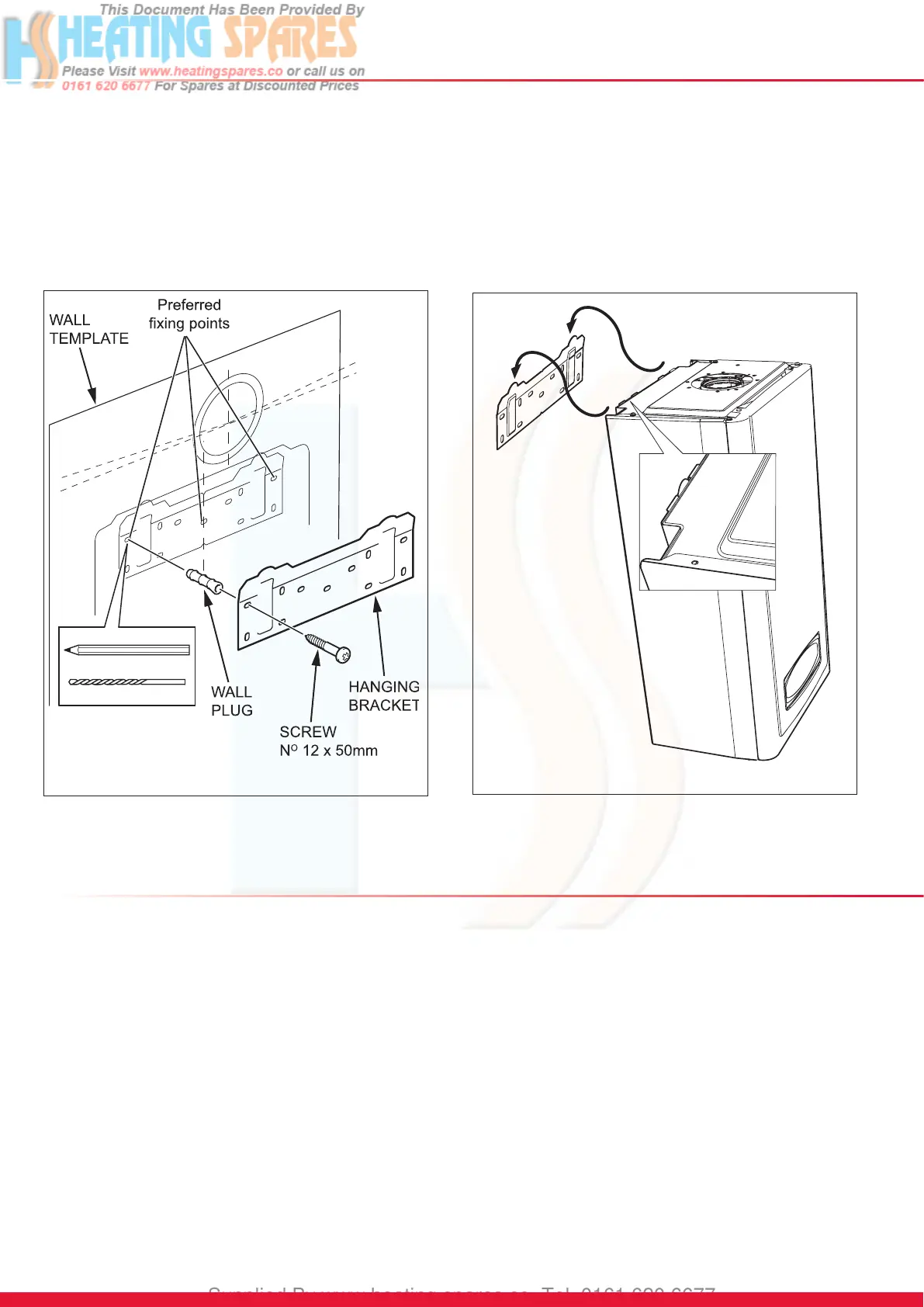
Details appliance packs, site requirements, fixing, and gas/water connections.

Safety Discharge & Condensate Handling

Details safe discharge valve installation and condensate drain connections.

Commissioning, Servicing & Fault Finding

Commissioning Procedures

Details steps for filling the heating circuit, water checks, and initial lighting.

Routine Servicing and Combustion Checks

Outlines general inspections, competency requirements, and combustion checks.

Fault Finding and Diagnostics

Explains fault codes, diagnostic menus, status codes, and troubleshooting steps.

Replacement of Parts & Spare Parts

General Part Replacement Procedures

Covers safety, draining, and general precautions before replacing appliance components.

Key Component Replacement

Details replacement steps for major parts like gas valve, fan, burner, and heat exchanger.

System Components & PCBs

Covers replacement of sensors, pumps, valves, PCBs, and interface modules.

Spare Parts Identification

Lists part numbers, descriptions, and GC part numbers for ordering spare components.

Manual Handling

Safe Lifting and Positioning Guidelines

Provides recommendations for safe lifting and positioning of the appliance during installation.

EC Declaration of Conformity

Compliance with Directives and Standards

States appliance compliance with relevant EU directives and European standards.

Related product manuals