Supplied By www.heating spares.co Tel. 0161 620 6677
42
13 Servicing
General Inspection
Prior to, during servicing and after any maintenance or
changed parts, the following must be checked.
● The integrity of the ue system and ue seals.
● The integrity of the appliance combustion circuit and
relevant seals.
● Electrical, gas and water connections.
● System pressure.
● the combustion performance, refer to the following
procedure.
● The operational gas inlet pressure and gas rates, refer to
the commissioning section paragraph 12.5.
Correct any fault before continuing.
COMPETENCY TO CARRY OUT THE CHECK
OF COMBUSTION PERFORMANCE
NOTE: BS 6798: 2009 Specication for installation and
maintenance of gas-red boilers of rated input not exceeding
70kW net advises that:
● The person carrying out a combustion measurement must
be assessed as competent in the use of a ue gas analyser
and the interpretation of the results.
● The ue gas analyser used should be one meeting the
requirements of BS7927 or BS-EN50379-3 and be calibrated
in accordance with the analyser manufacturers’ requirements.
● Competence can be demonstrated by satisfactory
completion of the CPA1 ACS assessment, which covers
the use of electronic portable combustion gas analysers in
accordance with BS 7967, parts 1 to 4.
● Ensure that the gas analyser is set to the correct fuel
setting.
● Turn both temperature control knobs on the fascia to
maximum.
NOTE: Safe combustion can only be veried by measuring
CO/CO2 ratio. This must not exceed the value shown in the
table opposite.
COMBUSTION CHECK AND SETTING THE AIR/
GAS RATIO VALVE
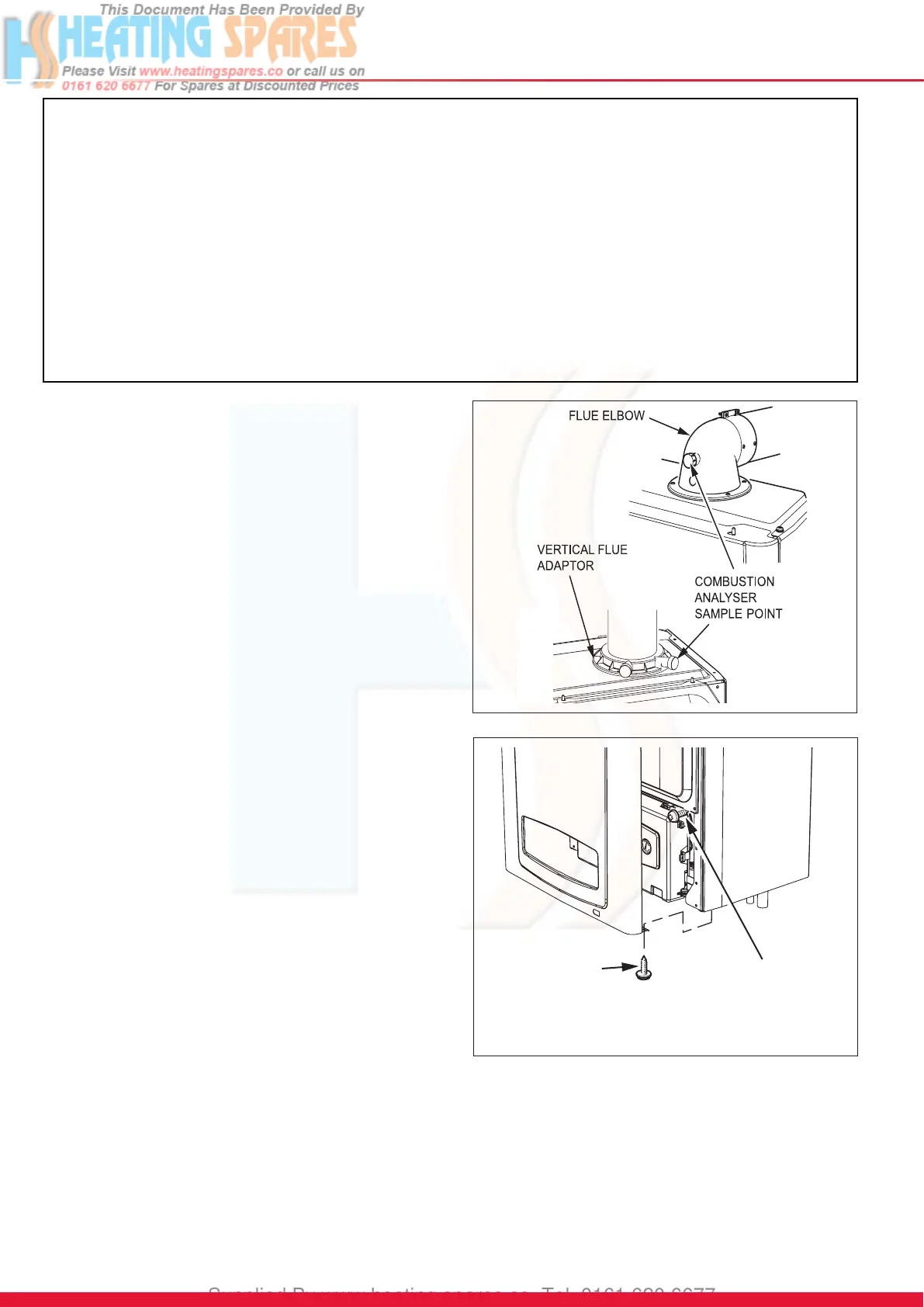
● Remove the front casing panel, see diagram 13.2 and hinge
down the control box. Taking care not to touch any internal
components, proceed as follows:
● Connect the CO2 combustion analyser to the relevant test
point, see diagram 13.1.
Diagram 13.2
FRONT
CASING PANEL
SECURING
SCREWS (2 OFF)
INNER CASING P
SECURING
SCREWS (2 OFF)
13232
IMPORTANT NOTES:
1. To ensure the continued efcient and safe operation of the boiler it is recommended that it is checked and serviced at
regular intervals. The frequency of servicing will depend upon the particular installation and usage, but in general once a
year should be enough.
2. It is the Law that any servicing is carried out by a competent person approved at the time by the Health and Safety
Executive.
3. Before commencing with a service or replacement of parts the boiler should be isolated from the electrical supply and the
gas supply should be turned off at the gas isolation valve.
4. When replacing a part on this appliance, use only spare parts that you can be assured conform to the safety and
performance specication that we require. Do not use reconditioned or copy parts that have not been clearly authorised
by Glow-worm.
5. If any electrical connections have been disconnected and after their connection, checks to the earth continuity, polarity,
short circuit and resistance to earth must be repeated using a suitable multimeter, as described in section 14.
6. After servicing, complete the relevant Service Interval Record section of the Benchmark Checklist located in the centre
pages of this document.
Diagram 13.1
13566
 Loading...