Supplied By www.heating spares.co Tel. 0161 620 6677
60
15 Replacement of Parts
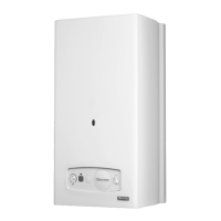
15.19 Domestic Hot Water Thermistor
For access, refer to section 15.1.
Refer to diagram 15.14.
Disconnect the domestic hot water thermistor electrical
connections
Remove hot water thermistor and retaining clip.
Remove domestic hot water thermistor from clip.
NOTE: When reconnecting electrical connections, polarity is
not important.
Carry out a functional test of the controls.
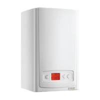
15.20 Automatic Air Vent
For access, refer to section 15.1.
Drain the boiler heating circuit as described in the appropriate
section of 15.1.
Refer to diagram 15.15 and gain access through the plastic
maintenance cover.
Unscrew the automatic air vent.
Fit the new automatic air vent and ‘O’ ring ensuring the vent
cap is left loose.
Rell, vent and pressurise the boiler.
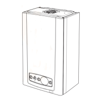
15.21 Low Water Pressure Sensor
For access, refer to section 15.1.
Drain the boiler heating circuit as described in the appropriate
section of 15.1.
Refer to diagram 15.16.
Disconnect the electrical lead.
Remove the retaining clip, remove the low water pressure
sensor.
Fit new ‘O’ ring.
Fit the new low water pressure sensor.
Rell vent and pressurise the boiler.
13258
Diagram 15.15
AUTOMATIC
AIR VENT
RETAINING
CLIP
COVER
13315
Diagram 15.14
13550
Diagram 15.16
 Loading...