Supplied By www.heating spares.co Tel. 0161 620 6677
63
15 Replacement of Parts
Diagram 15.22
13313
15.27 Appliance Interface and Main PCB
For access, refer to section 15.1.
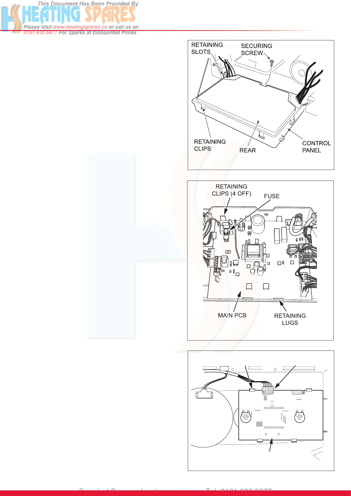
Remove control box retaining screw, see diagram 15.21.
Hinge down the control box.
Release the control box cover by carefully pressing the four
retaining latches, see diagram 15.21.
15.28 Main PCB
IMPORTANT: When replacing the board refer to instructions
supplied with the replacement.
For access, refer to section 15.27.
Remove the electrical connections to the PCB.
Ease back the four PCB retaining clips and withdraw the PCB
from the retaining lugs, see diagram 15.22.
When retting the rear panel ensure the leads are not
trapped.
When replacing the board refer to instructions supplied with
the replacement.
15.29 Appliance Interface
IMPORTANT: When replacing the board refer to instructions
supplied with the replacement.
Refer to section 15.27 for access.
Remove main PCB, refer to section 15.28.
Remove electrical connection.
Gently ease back the retaining clips, see diagram 15.23.
Withdraw the board.
15.30 Fuse, Main PCB - Control Box
For access, refer to section 15.27.
The fuse is located at top left hand side of the PCB, see
diagram 15.22.
15.31 Control Box
For access, refer to section 15.27.
Remove relevant plugs and connectors, refer to wiring
diagram 14.4.
Withdraw grommets and leads so they are hanging loose.
Unthread the retaining cord and remove the control box by
drawing it outwards away from its retaining slots, see diagram
15.21.
15.32 Inner Casing Panel Seal
For access, refer to section 15.1.
Refer to diagram 13.8.
Remove the inner casing panel.
To replace remove the old seal, thoroughly clean the casing
surfaces. Fit the new seal, it is supplied to the correct length.
Ret the inner casing panel.
NOTE: Ensure the seal is tted correctly giving an airtight
joint.
Diagram 15.21
13535
APPLIANCE INTERFACE
BOARD
CLIPS
CONNECTION
Diagram 15.23
13671
 Loading...