Supplied By www.heating spares.co Tel. 0161 620 6677
55
15 Replacement of Parts
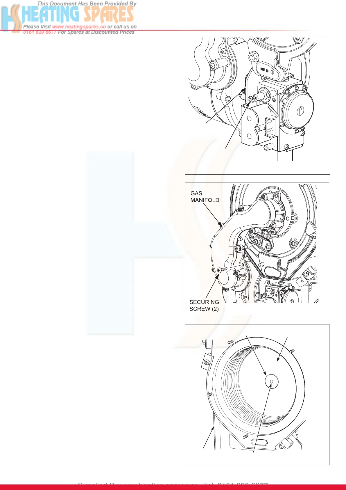
15.5 Gas Valve
For access, refer to section 15.1.
Refer to section 13.3 for removal of the fan, gas valve and
burner assembly.
Before removing the gas valve note its orientation in
relationship to the fan.
Remove the three securing screws, which also secures the
plastic swirl plate to the venturi on the fan, see diagram 15.2.
Withdraw the gas valve.
After assembly test for gas tightness and purge in accordance
with the current issue of BS6891or in IE, the current edition of
I.S.813 “Domestic Gas Installations”.
Check the combustion CO
2
and adjust if necessary, see
section 13.
15.6 Fan
For access, refer to section 15.1.
Refer to section 12.3 for removal of the fan, gas valve and
burner assembly.
Remove the gas valve as described in section 15.5.
Remove the two securing screws, nuts and washers to
separate the fan from the gas manifold extension tube and
gas manifold, see diagram 15.3.
After assembly test for gas soundness and purge in
accordance with the current issue of BS6891or in IE, the
current edition of I.S.813 “Domestic Gas Installations”.
15.7 Burner
For access, refer to section 15.1.
Refer to section 13.3 for removal of the fan, gas valve and
burner assembly.
Remove the four screws that secure the burner, see diagram
13.7.
NOTE: The burner will require a new gasket.
15.8 Front Insulation
For access, refer to section 15.1.
Refer to section 13.3 for removal of the burner module.
Remove burner as described in section 15.7.
Remove spark electrode, see section 15.2.
NOTE: The burner will require a new gasket when retted.
15.9 Rear Insulation
For access, refer to section 15.1.
Refer to section 13.3 for removal of the burner module.
Remove securing screw and washer in the centre of the
insulation and withdraw insulation, see diagram 15.4.
13238
SECURING SCREW
HEAT
EXCHANGER
WASHER
INSULATION
Diagram 15.4
13277
Diagram 15.3
13276
VENTURI
PLATE
SECURING
SCREW (3)
Diagram 15.2
 Loading...