[page 22] | gpelectric.com
3.5.6 WIRING THE INVERTER/CHARGER TO THE BATTERY BANK
WARNING: Lethal currents will be present if the positive and negative cables attached to the battery bank
touch each other. During the installation and wiring process, ensure the cable ends are insulated or covered
to prevent shorting the cables.
WARNING: DO NOT connect the DC Wires from the battery bank to the Inverter/Charger until all the DC and
AC wiring is complete and the AC and DC overcurrent protection has been installed.
The IC Series are 12V Inverter/Chargers so the battery bank must be wired in series, parallel, or series-parallel to provide the
correctvoltage:12V.Examplebatterycongurationsareshownonpage23.Theinterconnectingwiresbetweentheindividual
batteries must be sized and rated exactly the same as those used between the battery bank and Inverter/Charger.
For the IC Series to perform optimally a 200Ahr battery bank must be used for light/moderate loads (<1000W) and for heavy
loads of 1000W> a 400Ahr battery bank is recommended.
To ensure the best performance from your Inverter/Charger system, batteries should be the same size, type, rating, and age.
Do not use old or untested batteries.
WARNING: The Inverter/Charger is not reverse polarity protected. If the Inverter/Charger is wired incorrectly
severe damage will occur and will not be covered by the warranty. It is advised to clearly mark the positive
and negative cables coming from the battery bank. Use red and black electrical tape to clearly indicate
positive and negative cables.
DC Positive and Negative Wires
• Connect the negative cable from the battery bank negative terminal to the Inverter/Charger’s negative terminal.
Mount the DC circuit breaker or fuse assembly and leave open (no power to the GP-IC-2000). Connect the positive
cables from the circuit breaker/fuse to the battery bank and to the Inverter/Chargers positive terminal.
•
EnsuretheDCwireconnectionsareushonthesurfaceoftheDCterminalsandthehardwareusedtoholdthese
connections are stacked correctly. Verify all DC connections are secured tightly.
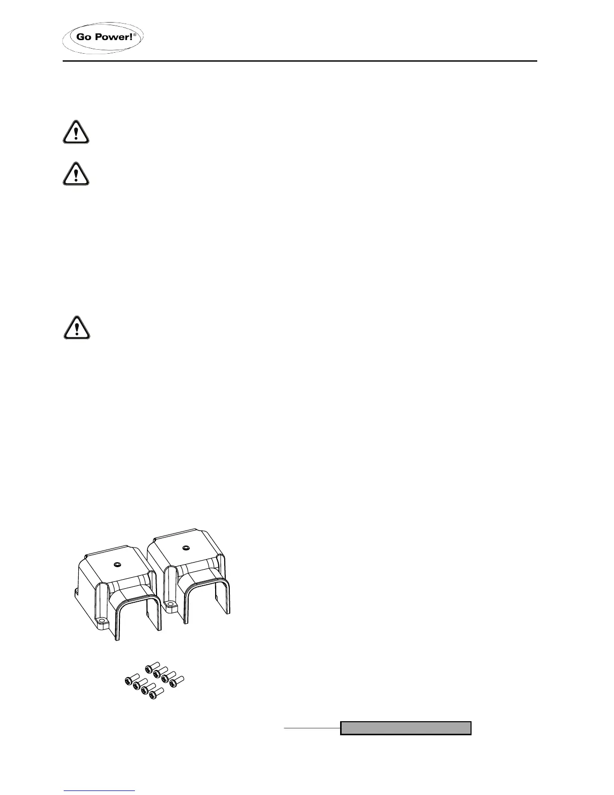
• Attach the red and black terminal covers (see below) over the Inverter/Charger’s DC connectors and secure them
in place with the supplied screws.
INSTALLATION
 Loading...