[page 30] | gpelectric.com
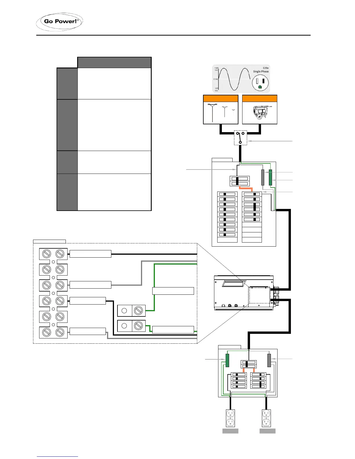
3.6.6 AC WIRING 1 - Single Phase, ≤30A Service, Single IN/Single OUT
INSTALLATION
IN 1
AC Hot 1 from main panel
ACN-IN
AC Neutral from main panel
AC Ground
AC Ground from main panel
OUT 1
AC Live to sub panel
ACN-OUT
AC Neutral to sub panel
AC Ground
AC Ground to sub panel
Single Phase - ≤30 Amp Service
Generator Power
120/240 VAC
OUT 1
AC Live to sub panel
ACN-OUT
AC Neutral to sub panel
(located within the GP-IC-2000)
50A @ 120VAC (Hot 1)
50A @ 120VAC (Hot 2)
Note: Loads must be correctly balanced between both
phases (Hot 1 and Hot 2) on the breaker panels in order to
Split Phase - ≤50 Amp Service
Install Option 2
AC Ground
AC Ground from main panel
AC Ground
AC Ground to sub panel
OUT 2
AC Live to sub panel
Transfer Switch
(only required if using
a hardwired generator
(located within the GP-IC-2000)
Transfer Switch
(only required if using
a hardwired generator
Maximum 30A Breaker
(single pole)
Notes:
* All previous converter/charger wiring must be disconnected from the
breaker panel. The IC Series is now used for battery bank charging.
Notes:
* Using wiring option 2 for 50 Amp service will allow all AC devices to be
powered from the IC Series in Inverting mode. Running devices that
use more than 2000-3000W (depending on your unit) will cause the Inverter/
Charger to go into overload. Operating high current draw loads (such as air
conditioning units) could severely deplete the battery bank power quickly.
* All previous converter/cherger wiring must now be disconnected from the
breaker panel. The IC Series is now used for battery bank charging.
.
 Loading...